diy solar

diy solar

Short through cell film

driew

New Member
Joined
Sep 25, 2021
Messages
5
Hi all!
This wasn't supposed to be the kind of first thread I make, but thought I would share a... could have been way bad... situation that I had a fortunately mild outcome from but could easily have devastating results.

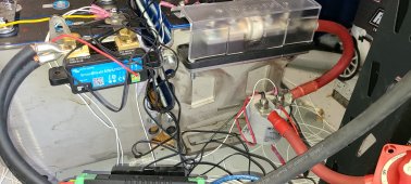
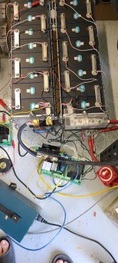
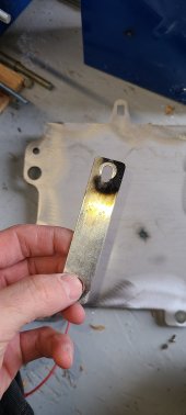
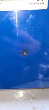
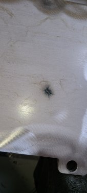
I was in the process of getting fixture plates laser cut and making adjustments to the template and thought just a quick test wouldn't hurt. I didn't have insulating material between the cells and the fixture plates and I think a spec of weld splatter or a sand granule punctured the side of the cell film on my most positive cell. I then was disassembling the cell pack to take my findings in to make adjustments to the drawings for a new cut and touched the most negative busbar against the fixture. I had planned to make the fixture and frame work all negative ground anyway so it didn't cross my mind of the possibility of a short circuit. I also had already removed the positive fuse. But BANG! The flash shooting up the positive terminal was far brighter than the actual cause of the short on the negative.

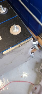
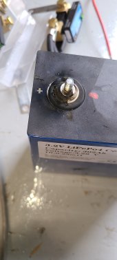
The cell melted through the aluminum casement on the sides and around the post. It is leaking electrolyte out of the side and top. (by the way, how should I now dispose of this leaking cell, it is/was around 30-40% SoC?).

What is interesting to me, is that the way the aluminum burned rapidly around the post itself, reminds me a lot of https://diysolarforum.com/threads/last-fire.25937/ 's fire and I wonder if he had cell casing to cell casing short that triggered his.

I had planned to put cnc routered insulators between the plates and cells and then strips of pvc liner between each cell. And pvc tubing on the threads (have it on the bottom rods, but not the sides in my test setup, as I was being "careful" to not touch the cells).

The real bummer is that I had 4 extra cells I meant to use as a way to sort out the weakest capacity cells and then use those 4 in my rv. Now I have an odd series count and will have 'spares' I suppose.
 

Attachments

  • 2021-10-26 15.11.51.jpg
    2021-10-26 15.11.51.jpg
    82.4 KB · Views: 97
  • 2021-10-26 15.11.47.jpg
    2021-10-26 15.11.47.jpg
    65.6 KB · Views: 98
  • 2021-10-26 15.11.29.jpg
    2021-10-26 15.11.29.jpg
    63.8 KB · Views: 99
  • 2021-10-26 15.11.25.jpg
    2021-10-26 15.11.25.jpg
    75.7 KB · Views: 99
  • 2021-10-26 15.11.21.jpg
    2021-10-26 15.11.21.jpg
    112.6 KB · Views: 97
Sorry for your mishap.
Do you have a 4s, 8s or 16s package ?
This was definitely a case-to-fixture short (on one side).
Was it a single cell sort (so 3,2V) or a more cell short?
I read your description several times and still can not imagine it :)
 
It is in a 16s arrangement with 2x 8s fixture assemblies in series (8s pack is not bad to carry).

It was worst case actually, most positive cell is the one that shorted to fixture, and it was the most negative terminal that shorted when I was disassembling. After the short and a bit of confusion, negative to fixture was 53.2v! It was definitely a bit hairy knowing how to disassemble that after, I was really worried about another possible short somewhere that I couldn't see.

Here are a few more pictures of the test setup, the final setup will have the string all in one long row mounted to the wall. I have 4x 16s packs to assemble this way. They will be each fused and then joined together on a busbar in parallel before going through a 1000a batrium shunt into two 15kva Victron Quattro inverters with 84x 280watt Sunpower pv modules. My first thread was supposed to be a discussion about my planned system, not this!

But this has definitely increased the level of insulation I am planning on. I'll post some pictures of the insulators once I come up with something. Likely some routered delrin sheet or something else suitable.

The whole reason I have this test arrangement was to do tests on the batrium shunt as my current inverter (sigineer m12kw) is noisy and is causing the shunt to read incorrectly at certain amp draws. That's why I have the victron shunt dangling off the post like that in series. The plan will be to have a welded support base with a negative terminal stud and busbar just like the fuse block that way cabling is not pulling on the cell terminal but instead an insulated stud block.

Edit: Probably the biggest factor in this not getting way worse, is that the two fixture assemblies were merely touching each other side by side and not actually bolted together. It 'self-cleared' the short after it's initial bang.
 

Attachments

  • 2021-10-21 14.06.49.jpg
    2021-10-21 14.06.49.jpg
    362.2 KB · Views: 59
  • 2021-10-21 14.06.45.jpg
    2021-10-21 14.06.45.jpg
    152.1 KB · Views: 60
It is in a 16s arrangement with 2x 8s fixture assemblies in series (8s pack is not bad to carry).

It was worst case actually, most positive cell is the one that shorted to fixture, and it was the most negative terminal that shorted when I was disassembling. After the short and a bit of confusion, negative to fixture was 53.2v! It was definitely a bit hairy knowing how to disassemble that after, I was really worried about another possible short somewhere that I couldn't see.
The most negative? I think first you shorted a string of 8s cells ... but 16s ... that is the worst.
The two cells on the ends are toast ... but the others survived ?

Here are a few more pictures of the test setup, the final setup will have the string all in one long row mounted to the wall. I have 4x 16s packs to assemble this way. They will be each fused and then joined together on a busbar in parallel before going through a 1000a batrium shunt into two 15kva Victron Quattro inverters with 84x 280watt Sunpower pv modules. My first thread was supposed to be a discussion about my planned system, not this!
That will be a huge system. Nice :)
You will use Batrium BMS too ?
Do you make a separated off-grid, or off-grid with grid support setup?

But this has definitely increased the level of insulation I am planning on. I'll post some pictures of the insulators once I come up with something. Likely some routered delrin sheet or something else suitable.
The best is FR4 fiber glass sheet I think (like 0,5mm). All around the cells, between the cells and the case ....
Check @Will Prowse last battery test/teardown video:
Finally a battery well made.


The whole reason I have this test arrangement was to do tests on the batrium shunt as my current inverter (sigineer m12kw) is noisy and is causing the shunt to read incorrectly at certain amp draws. That's why I have the victron shunt dangling off the post like that in series. The plan will be to have a welded support base with a negative terminal stud and busbar just like the fuse block that way cabling is not pulling on the cell terminal but instead an insulated stud block.

Edit: Probably the biggest factor in this not getting way worse, is that the two fixture assemblies were merely touching each other side by side and not actually bolted together. It 'self-cleared' the short after it's initial bang.

One guy did this case here ... and I like it.
How cool is that? (except he forgot the plates on the end, and no way to compress, and the isolation is not perfect .... but it looks amazing :) )

Lishen_with_alu_case.jpg
 
The most negative? I think first you shorted a string of 8s cells ... but 16s ... that is the worst.
The two cells on the ends are toast ... but the others survived ?
It was very chilling just how quickly it could have been worse. The fault cleared itself, so after a bang it wasn't still in meltdown. The burns around the terminal post all happened in a single flash, it was a bang with a blinding rose bud flare coming around that positive busbar, imagine a dirty acetylene torch tip and then it was over.

Yep, full 16s pack short. Only the most positive cell had damage, I cannot find any issues with any of the other 15 cells so far. Just a few dark spots in the black plastic cell top where molten aluminum landed on the neighboring cells.

That will be a huge system. Nice :)
You will use Batrium BMS too ?
Do you make a separated off-grid, or off-grid with grid support setup?

Go big or go home! Haha
Yep, I'm using Batrium in a multi-string setup using Cellmate K9s. I may later on use two Batriums and have 2 parallel "systems" of 2x multi-string packs. That way I can fully take a "system" offline and have the rest still be connected to the inverters.
That will depend on if I can actually integrate two batriums into two victron inverters that are operating together without issue. I'm still unsure if that's possible.
Batrium is quite impressive, out of the box I was able to assemble my pack, charge it up and 52 hrs later I had a top balanced pack. I tried that with a Daly BMS on a 4s pack and was unimpressed at the really weak balancing ability of that thing.
I would never bother with a parallel top balance with Batrium, but I would with other cheap BMSs.

My system is a grid-backed system intended to use solar and time of day grid power ("self consuming ess" in Victron speak). I have a constant 11kw load from bitcoin mining that I plan to operate from this system along with my house. It's my "backup generator" if there is grid failure. I'm somewhere in a 4year ROI once the system is fully online. Might be closer to 5 year by the time the little nickel and dime purchases are over with. The fuses alone have been an unexpected sticker shock!

The best is FR4 fiber glass sheet I think (like 0,5mm). All around the cells, between the cells and the case ....
Check @Will Prowse last battery test/teardown video:
Finally a battery well made.
I will check that out! Thank you!

One guy did this case here ... and I like it.
How cool is that? (except he forgot the plates on the end, and no way to compress, and the isolation is not perfect .... but it looks amazing :) )

View attachment 70345
That actually looks pretty cool! However, I would be really concerned about having no fixture plates with busbars like that, it was shocking how much the cells want to expand when brought up above 3.45v per cell. In my fixture, when the cells are 20% SoC (and left to rest for a day) I could loosen my allthread nuts with my fingers, once charged and absorbed to 3.45v-3.5v, you could lift the entire pack as a single unit with no flex at all. You could also feel the allthread being tight and there is a measurable stretch in the allthread from the pack pressure.
 
It is in a 16s arrangement with 2x 8s fixture assemblies in series (8s pack is not bad to carry).

It was worst case actually, most positive cell is the one that shorted to fixture, and it was the most negative terminal that shorted when I was disassembling. After the short and a bit of confusion, negative to fixture was 53.2v! It was definitely a bit hairy knowing how to disassemble that after, I was really worried about another possible short somewhere that I couldn't see.

Here are a few more pictures of the test setup, the final setup will have the string all in one long row mounted to the wall. I have 4x 16s packs to assemble this way. They will be each fused and then joined together on a busbar in parallel before going through a 1000a batrium shunt into two 15kva Victron Quattro inverters with 84x 280watt Sunpower pv modules. My first thread was supposed to be a discussion about my planned system, not this!

But this has definitely increased the level of insulation I am planning on. I'll post some pictures of the insulators once I come up with something. Likely some routered delrin sheet or something else suitable.

The whole reason I have this test arrangement was to do tests on the batrium shunt as my current inverter (sigineer m12kw) is noisy and is causing the shunt to read incorrectly at certain amp draws. That's why I have the victron shunt dangling off the post like that in series. The plan will be to have a welded support base with a negative terminal stud and busbar just like the fuse block that way cabling is not pulling on the cell terminal but instead an insulated stud block.

Edit: Probably the biggest factor in this not getting way worse, is that the two fixture assemblies were merely touching each other side by side and not actually bolted together. It 'self-cleared' the short after it's initial bang.
I am trying to wrap my head around what shorted.

I am TERRIFIED of the metal end plates in your picture with the lugs nigh touching the main negative and main positive connections, and the plates nearly touching each other.
 
I am trying to wrap my head around what shorted.
Do you see the Victron Smartshunt precariously hanging off the negative terminal in my later post? As I was disassembling that, I began to loosen the negative nut and the weight of the shunt pulled the busbar down into the fixture plate. I wasn't "worried" about this happening because I expected all of the metal things to be floating or negative ground. (I will have a negative grounded system when complete).

However, the most positive cell was already rubbed thru and had the fixture plates at a positive potential without me knowing it.

In my first picture, you can see a little melted spot in the fixture plate, that's where the shunt busbar touched. No burns or marks on the cell terminal or nut, crazy!
I am TERRIFIED of the metal end plates in your picture with the lugs nigh touching the main negative and main positive connections, and the plates nearly touching each other.
I have allthread below the cells as well, the end plates cannot slide up into the busbars even when everything is loose, and yes, the left and right fixture plates were touching each other which is how the current flowed from the positive cell into the fixture plate on the right, into the fixture plate on the left up into the now touching negative busbar thru the pack into the positive cell's body.
 
Back
Top