diy solar

diy solar

Signature Solar EG4 6.5K Off-Grid Inverter | 6500EX-48

Hi All, hoping for some guidance. Read through most of this thread, watched all of wills videos, and am following his instructions/diagrams as well as the grounding/bonding one from Filterguy(my setup is closest to slide 2) and am still a bit puzzled.

I have (1) 6500EX + 15kwh Eg4 48v server racked batteries + 4000w array. Completely off-grid.

I am planning to use my generator (I believe floating ground) as a backup to charge the batteries through the inverter. I also would like to have the option to wire/plug the generator directly to the panel (in case the inverter stops working). Generator: Predator 3500 inverter/generator.

Questions:
1. Do I need a transfer switch or can I just wire a receptacle for my generator into the main panel for if/when I should ever need to bypass the inverter?
2. How do I ground? from what I have gathered I need to ground the main panel with a "system bonding jumper" to a grounding rod(or chassis?) but a professional should do this piece (not very clear on that).
3. Does the generator need a Neutral Ground Bonding Plug?
4. For the "NG Bond Disabled" in the diagram (slide 2) is this automatic, a software setting, or a manual configuration?

Thank you so much!!!
 
Last edited:
Hi All, hoping for some guidance. Read through most of this thread, watched all of wills videos, and am following his instructions/diagrams as well as the grounding/bonding one from Filterguy(my setup is closest to slide 2) and am still a bit puzzled.

I have (1) 6500EX + 15kwh Eg4 48v server racked batteries + 4000w array. Completely off-grid.

I am planning to use my generator (I believe floating ground) as a backup to charge the batteries through the inverter. I also would like to have the option to wire/plug the generator directly to the panel (in case the inverter stops working). Generator: Predator 3500 inverter/generator.

Questions:
1. Do I need a transfer switch or can I just wire a receptacle for my generator into the main panel for if/when I should ever need to bypass the inverter?
2. How do I ground? from what I have gathered I need to ground the main panel with a "system bonding jumper" to a grounding rod(or chassis?) but a professional should do this piece (not very clear on that).
3. Does the generator need a Neutral Ground Bonding Plug?
4. For the "NG Bond Disabled" in the diagram (slide 2) is this automatic, a software setting, or a manual configuration?

Thank you so much!!!
How did you end up wiring the generator inputs?
 
Hi All, hoping for some guidance. Read through most of this thread, watched all of wills videos, and am following his instructions/diagrams as well as the grounding/bonding one from Filterguy(my setup is closest to slide 2) and am still a bit puzzled.

I have (1) 6500EX + 15kwh Eg4 48v server racked batteries + 4000w array. Completely off-grid.

I am planning to use my generator (I believe floating ground) as a backup to charge the batteries through the inverter. I also would like to have the option to wire/plug the generator directly to the panel (in case the inverter stops working). Generator: Predator 3500 inverter/generator.

Questions:
1. Do I need a transfer switch or can I just wire a receptacle for my generator into the main panel for if/when I should ever need to bypass the inverter?
2. How do I ground? from what I have gathered I need to ground the main panel with a "system bonding jumper" to a grounding rod(or chassis?) but a professional should do this piece (not very clear on that).
3. Does the generator need a Neutral Ground Bonding Plug?
4. For the "NG Bond Disabled" in the diagram (slide 2) is this automatic, a software setting, or a manual configuration?

Thank you so much!!!
I called Signature Solar with related questions and was told point blank to not hook up a low-cost, portable generator through any inverter. Unless you have proof your generator produces <5% Total Harmonic Distortion (THD), you risk frying sensitive electronics like the inverter (and if you're bypassing the inverter to power your house directly, you also risk damage to plugged-in devices in your home, unless you have 'line conditioners' between the generator & electronics).

SS strongly recommended using a low-cost generator to power a bank of battery chargers that are wired to your batteries' busbars. Then, run your house off charged batteries.

Both line conditioners & battery chargers have transformers in them that isolate the generator's noisy voltage from downstream appliances/batteries. An EG4 18amp battery charger will draw ~11 amps from your generator, so unless you upgrade your generator a bunch & buy a handful of EG4 DC chargers, you're going to be waiting a long time to charge up depleted batteries...
-or-
Buy some Tripp line conditioners, plug your smart toaster oven in a big one & all your media electronics in a smaller one & backfeed your panel with your generator. You only need a transfer switch if you (or others) are prone to spacing out about shutting off the inverter's circuit breaker before energizing the panel from the generator. Usually those fail-safe items are associated with grid-tied setups, to protect line workers.

As for grounding, if your main panel (that either the inverter or your generator feeds electricity into) is where the system's neutrals are bonded to the Earth ground, then that is adequate (at least according to my Generac portable generator's manual... They say a grounding rod is only required when the generator is operating in a standalone situation, like at a construction site.)

I HTH...
 
True, the box store Chinese generators have dirty power, Westinghouse, Duromax, Champion, etc. Only use a quality Winco or any of the few using a Mecc-Alte generator head or an inverter generator. Most inverter models are <3% THD by nature of design.
 
Thanks for your input. If inverters are <3% typically, how can it be that page 7 of the 6500EX's manual not only lists that exact spec but it also (at the bottom of the page) cites <10% for non-linear loads (like PCs, TVs & other electronics). And, to top it off, Signature Solar says they both are valid. How can this be? (Not that I expect you to justify SS's manual, but it seems you know a lot about inverters and THD.). Thanks!
 
Last edited:
Their manuals are translated as best they can I suppose, a lot of discovery is trial and error. This is A go-to explanation of generator characteristics
Box store equipment is usually >25% THD or more. Your new Trane variable furnace boards won't last long with that power.
"In a traditional generator, the power produced by the alternator is fed (more or less) straight to the control panel. It may go through a voltage regulator or other protective devices, but the power is not necessarily “cleaned up”. Therefore, the power produced by a traditional generator has a higher total harmonic distortion (THD) than the power produced by an inverter generator. THD is a measure of how clean the power is – more on that in a moment.

An inverter generator works differently. The alternating current (AC) power produced by the alternator is sent to a rectifier, which is a device that converts the AC power to direct current (DC). This DC power is then inverted back to AC power by the computer inside the generator before it is sent to the control panel. This is where the name “inverter” comes from. Because the power to the control panel is controlled by the computer, inverter generators offer much lower THD than standard generators. THD is an important consideration when powering sensitive devices, like smartphones, tablets, computers, and televisions. These devices expect “clean” power (power that has low THD, like the wall power in your home), and can be damaged if they receive high-THD power. All WEN inverter generators use pure-sine-wave inverters, and as such, limit THD to under 1% in most cases. Traditional generators can produce THD as high as 25% in some cases." There are a few exceptions to this rule, 12K Westinghouse and the cleaner generators will actually include the THD in the specs. People buying these have no clue what it is anyway..
 
Anyone having or seen this type of problem: 120V, 2P1 and 2P2 180. @BenFromSignatureSolar

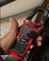
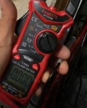
With the inverter AC input breaker off, which is the garage subpanel, the reading on neutral and ground busbars is 0.0A. When the breaker is turn on, with the inverters in standby and charge with solar only, the reading fluctuates between 0.014 - 0.023A. After changing the inverters to charge with solar AND utility the reading increases and fluctuates between 0.100 - 0.080A.

When the AC input breaker is on a low hum and soft arcing(?) sound can be heard in the MAIN panel. Cannot pinpoint but does sound the loudest coming from underneath the left side of the panel. The panel is mounted on plywood and the 100A breaker for the subpanel in the garage is on the right side.

It has done this since the first day (09NOV22) with both inverter N-G bond screws in, only one N-G screw in and with both out; same variation with and without common neutral. Other than this everything seems to work fine, but because of it I leave the AC input off.

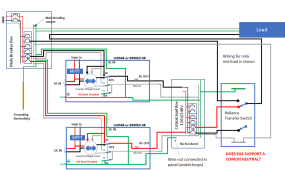
This is the configuration and a picture of the reading:

1654122382016 MTS.png


.023A AC Input breaker on.jpg
0.0 reading.jpg
 
I had this issue in a panel one time. It was one of the 20A plug-in breakers that had arced long enough to corrode the metal, so it wasn't making good contact. It got louder when loaded, and stopped when I pushed on it. As for the 100mA of leakage current, there is capacitance between L-G, so it's probably the EMI filter. Is the leakage still there when you put the screws back in the inverters?
 
I had this issue in a panel one time. It was one of the 20A plug-in breakers that had arced long enough to corrode the metal, so it wasn't making good contact. It got louder when loaded, and stopped when I pushed on it. As for the 100mA of leakage current, there is capacitance between L-G, so it's probably the EMI filter. Is the leakage still there when you put the screws back in the inverters?
Thanks for responding. It was doing this "before" I took them out; I have also pushed and wiggled all other breakers, without results. Could the load on any other breaker change by flipping on the inverter AC input breaker? I was supposing my next step would be to pull out each breaker and check for evidence of connection issues.

So, this amount of EMI filter leakage is minimal and nothing to be concerned about?
 
Stick a 60 w filament light bulb between neutral and earth, it it lights you have a serious problem lol. But I suspect most of it is just ever so small leakage current.
 
Thanks for responding. It was doing this "before" I took them out; I have also pushed and wiggled all other breakers, without results. Could the load on any other breaker change by flipping on the inverter AC input breaker? I was supposing my next step would be to pull out each breaker and check for evidence of connection issues.

So, this amount of EMI filter leakage is minimal and nothing to be concerned about?
If you're standing in water, it can be significant. I would check ground bonds between the equipment until I found where it was coming from and make sure it was well grounded.
 
On the original post for charging. I'm running (2) 6500EX 120/240 (2P1/2P2) offgrrid on their own main panel. I have an existing transfer switch for the grid main panel. I spoke to Signature Solar about my gen (6500W) and options.

Given either way I'd have to rewire my existing panels and transfer switch, I opted to purchase (5) of the 48V waterproof chargers. I'm going to wire the transfer switch to some quad outlets each on their own breakers from the transfer switch and charge batteries from generator through the 48V chargers direct to my main bus bars.
 
I opted to purchase (5) of the 48V waterproof chargers. I'm going to wire the transfer switch to some quad outlets each on their own breakers from the transfer switch and charge batteries from generator through the 48V chargers direct to my main bus bars.
Would like to see this. You are going to put 5 chargers onto the main bus bar?

Your setup sounds like what I am going to be facing - I have a 6500 geny and am trying to figure out how to run either grid or geny to the inverters (I also have 2 of the 6500) to recharge everything. Right now I only have 3 DIY batteries. May add more later.

Thanks
 
I'm assembling three 20a receptacles that will sit between 6 chargers and 3 of my generator's 4 120v outlets. The chargers will be wired to bus bars that are wired to the battery rack's bus bars.
 
On the original post for charging. I'm running (2) 6500EX 120/240 (2P1/2P2) offgrrid on their own main panel. I have an existing transfer switch for the grid main panel. I spoke to Signature Solar about my gen (6500W) and options.

Given either way I'd have to rewire my existing panels and transfer switch, I opted to purchase (5) of the 48V waterproof chargers. I'm going to wire the transfer switch to some quad outlets each on their own breakers from the transfer switch and charge batteries from generator through the 48V chargers direct to my main bus bars.
I'm looking at doing the same thing with 1 48v charger. I didn't know you could hook up multiple chargers to the busbar.
 
I am going to remove the clamps from the charger leads and replace them with copper lugs, then use a (2) 200A busbars to combine the + and -'s. From those two buss bars, I'm going to have (2) 2/0 leads to connect to my main battery busbars for charging when/if necessary.

This will let me run any number of chargers I want just by plugging them in. Giving me a range of 18A to 90A of charging. Doing it this way because besides the 6500W gen, I have a 2200W as well.
 
I'm looking at doing the same thing with 1 48v charger. I didn't know you could hook up multiple chargers to the busbar.

You can place charging power sources in parallel. The important thing for my situation is you need to remember the chargers are "dumb". They should not be left on without watching your state of charge as LiFePO4 shouldn't have a float voltage (unlike lead acid). Now my BMSs should protect the batteries, but still not something I would hook up and forget about.
 
You can place charging power sources in parallel. The important thing for my situation is you need to remember the chargers are "dumb". They should not be left on without watching your state of charge as LiFePO4 shouldn't have a float voltage (unlike lead acid). Now my BMSs should protect the batteries, but still not something I would hook up and forget about.
Could you use something like a smart shunt to help monitor the SOC with this configuration?
 
Yes, you can use a smart shunt to monitor. I have one I'm going to install on my setup so we'll have a quick look status in the kitchen.
 
Back
Top