diy solar

diy solar

Signature Solar EG4 6.5K Off-Grid Inverter | 6500EX-48

NEC 250.6 doesn't apply for a configuration that has been tested to UL1741 and certified for that purpose, even if it was done by TUV and not UL.
The NEC articles I think are applicable are 250.24 (Dual-Fed Services), para. (5)(C). Also, 250.30(6) Multiple Separately Derived Systems.

This drawing shows how to do it using a JB to enclose any "objectionable currents" between the multiple separately derived systems. Unbalanced loads are a reality, they can't be avoided. Grouping the inverters and considering them to be ONE unit is IMO, perfectly satisfactory.

View attachment 96565
That drawing has one n-g bond in inverter mode and 1 n-g bond in bypass mode.
That is not a topo that I would have a problem with.
I would have a problem if both AIOs hand N bonded to G.
 
But it is not possible when using more than one of these types of inverters, split-phase or in parallel. IMO, this is how TUV tested it to UL1741, so as long as you use it per the manufacturer's directions, it's fine. If it bothers you for no reason, use an AIMS LF inverter or a 240V inverter with a split-phase transformer. A split-phase configuration can't be done any other way with a 120V inverter. That's just the way it is.
Another alternative is to get a 120V to 120/240V split-phase isolation transformer. Then you have a new separately derived neutral to bond at your sub-panel that is isolated from the main panel.
Yes, I have come to realize some of the few downsides to these units and how they function with relation to the bonding. I also understand that some objectionable current over a short run of or protected and properly sized and grounded conductor will not likely be a risk or danger. I have seen lightning damaging equipment mentioned before but not sure how this would play into this debate.
I understand there are people that want as little and most minimized risk as possible, and I think that is why this is such a sticking point with these inverters. Also the fact that they have much to be desired in terms of documentation. I'm appreciated of the documentation that has been done on this forum and it sure helps the community.
 
That drawing has one n-g bond in inverter mode and 1 n-g bond in bypass mode.
That is not a topo that I would have a problem with.
I would have a problem if both AIOs hand N bonded to G.
Good catch. I knew I was forgetting one more thing I needed to change. It's fixed now. All grounded per UL1741 test certificate, as designed. Honestly I don't care if anyone wants to void their warranty and the TUV safety certification to have it their way. I'm just saying, it's not necessary for any sort of "compliance". It complies just the way it was tested, per the manufacturer's instructions. Testing to a UL standard means any conflict with NEC is over-ridden by the UL standard testing. It was tested for this application, in this configuration and deemed safe by TUV. That's all I or you need to know.
 
Last edited:
When the neutral is not switched, the inverter input and output neutrals are tied together. (See purple dashed line below)
OK, I think I understand the issue now, however as I indicated, in my setup, there's is no AC input whatsoever. It's a manual transfer switch so whenever I wish to use mains power I just flip the switch. Now if I was going to use AC inputs on the inverter, it would make more sense to use the internal transfer switch and eliminate the reliance. And this is where I'm seeing the major disagreements as to whether it's safe with or without the screw. Who is right? I don't know, but I don't want to make an expensive mistake.
 
OK, I think I understand the issue now, however as I indicated, in my setup, there's is no AC input whatsoever. It's a manual transfer switch so whenever I wish to use mains power I just flip the switch. Now if I was going to use AC inputs on the inverter, it would make more sense to use the internal transfer switch and eliminate the reliance. And this is where I'm seeing the major disagreements as to whether it's safe with or without the screw. Who is right? I don't know, but I don't want to make an expensive mistake.
My first inverter design passed UL1741 in 1988, and I was tasked with making sure every inverter we were manufacturing at Topaz, Inc. was ready to pass the standard when it was implemented and made mandatory. I've been doing this stuff for nearly 40 years, and I've been installing solar since 2010 in many major cities. I've been through over 500 permit reviews and inspections, in cities like LA, Santa Cruz, San Diego, Minneapolis, Parsippany, etc.., and I've learned what can and can't be done, per code. I was licensed in CA, but not in NC (yet), I'm ready to retire. What I'm saying is, you can trust what I say and take it to the inspector.
 
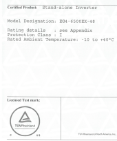
An inverter can be tested to UL1741 standard by UL, CSA or ETL and be "Listed", and this is acceptable to any AHJ Inspector I've ever worked with. The EG4 inverter says TUV Certified to UL1741 for compliance. It isn't "Listed" because TUV doesn't use that term. However, they are a Nationally Recognized Testing Laboratory (NRTL) that certifies products, just like UL, CSA and ETL. UL Listing and UL Recognized both fall under the category of "Certified", so there is some ambiguity because of their terminology. Some AHJ's may not be aware that the cTUVus mark is equivalent to a UL Listing when tested to the same standards, but that is changing.

"The cTUVus mark is officially recognized as an equivalent and direct replacement of the UL and CSA marks. UL is both a US standards body and a laboratory. National Recognized Testing Laboratories (NRTL) like TÜV Rheinland can test to the same standards and specifications as those defined by UL as US standards."

Your inverter doesn't need to be tested by "UL" to be acceptable anymore. Other laboratories are competing with UL, which is good because the cost is outrageous to get a product certified these days. The EG4 inverters bear the cTUVus Mark, which is equivalent to a UL Listing mark.

Screen Shot 2022-05-31 at 4.18.15 PM.png
 
If the AC from the mains is going to the switch and not through the 2 inverters, and the inverters are properly grounded with properly sized wires. Then there is no issue at all.
If the AC from the mains is going through the inverters, then you don't need the extra transfer switch and there is still no issue. The transfer switch is an unnecessary expense.
What was acceptable in the past has NO relevance in a new install.

Grounding conductors have two and only two jobs in modern home wiring…

Static and surge dissipation, and overcurrent fault path…

Designing a system using the grounding conductor to carry current is a path to problems, and is against modern codes.
 
However, after seeing these EG4 6500 units, this seems to be the solution to all of that because you can both get 240v service and you can get 120v service without the limits of an auto transformer. Additionally, you seem to be able to use multiple units on each 120v leg to have up to 19500W per 120v leg. Can someone please advise if I have missed something.

That seems to be the idea. I even seem to recall some of these AIOs manuals suggesting that you can stack legs disproportionately within a given range if your 120v needs far exceed your split-phase ones.

Potential downsides include paying extra efficiency costs (generally already higher per-unit), generally lower quality (presumably), more complicated wiring, more space usage.

On the flip side, it's easier to replace parts that fail if they fail one at a time.

This grounding discussion is pretty spicy, though.
 
i have a stupid question, unfortunately..whats the max amps the ac input can handle from utility? Is it the same as pv, 120a?
 
Last edited:
What was acceptable in the past has NO relevance in a new install.

Grounding conductors have two and only two jobs in modern home wiring…

Static and surge dissipation, and overcurrent fault path…

Designing a system using the grounding conductor to carry current is a path to problems, and is against modern codes.
If that is your stance, then for you there is absolutely no way to parallel or split-phase configure ANY 120V inverters, except to void the warranty and the TUV UL1741 safety certification by removing the internal "customer inaccessible" N-G bond.

However, I will remind you and everyone here again, that when a unit is tested to a UL standard in a particular configuration and deemed "safe", it overrides the NEC. I have an Enphase system I just installed where the IQ Combiner 4, combiner box does not comply with the 120% rule that a service panel must comply with. Enphase specifically calls out in their manual that the 120% rule is not applicable, the IQ Combiner 4 is Code Compliant because it was UL Listed for this specific application. The same should also be true for the EG4 Inverters, given their cTUVus Certification to UL1741.
 
I am grateful for your responses and time.

I was less than clear about the situation. There will two separate systems at the same house. Currently, one is a standard residential 240 split phase service panel that feeds my house. The solar system is intended to be an off-grid source of power during grid outages that will feed a non-grid connected mini-split heat-pump and enable connection of 12 AWG extension cables to run a freezer, refrigerator, and a few lights in case the grid goes down.

An EG4 6548 EX inverter and EG4 5.1kV battery will be delivered 2022-06-01. I was going to connect my main service panel's AC into the EG4 6548 EX via a 125A sub-panel for AC into the inverter. From what I understand, to avoid more than one N-G bond in the house's electric system the inverter's N-G bond screw would have to be removed in order to enable grounding the inverter via the AC input fed from the main service panel.

Unfortunately, there appears to be no feasible code-compliant/permittable way to connect an off-grid inverter that is not UL Listed to a sub-panel connected to a main service panel. In order to have a legal installation in my area, a UL listed off-grid inverter must be installed by a licensed electrician and the installation must meet National Electric and International Construction Codes. Currently, the EG4 6548 EX inverter is not UL Listed. In my area, without UL listing, an inverter will not be permitted to be connected to the grid via a sub-panel.

Upon the realization that my original plan was not feasible, my thought was to run an Equipment Grounding Conductor (EGC) from the ground of the inverter's AC output panel back to the main service panel. To avoid multiple N-G bond points, the inverter's AC output panel would not bond neutral to ground but would instead be bonded back at the main service panel via the EGC run from the ground terminal in the sub-panel.

To make sure I have only one N-G in the system, I was going to remove the N-G bond screw in the inverter as if AC input power from the main service was supplied. I am still not sure if bonding the inverter's AC output panel to the service main ground is allowed by code.

Diagram 2 above is almost exactly what I was thinking with the exception that the diagram shows the N-G bond screw is still connected in the inverter.
Please advise on two questions:
1) if the inverter output AC panel is connected via EGC back to the main service panel's ground bar, should the N-G bond screw in the inverter be removed?
2) Does connecting the EGC to the main panel violate NEC code?

I apologize to the pros on the forum if my thoughts are naive, I am grateful for thoughts on the matter.
 
I think people should stop relying on signature solar and others to figure out these products. I understand that they have a warranty and advertised use case, but if I had to ask them for help every two seconds, my channel would fail overnight. These systems are aimed at the diy market. When I am programming a microcontroller, I'm not asking the manufacturer every question I have. I'll find a way to make it work without asking for help.

And Richard works hard responding to questions. I feel bad for him. I appreciate what he contributes. It would be nice if some of you could say thanks Richard from time to time. And I'm not standing up for signature solar or any other solar equipment distributor. But man, they work a lot.
Totally agree, provided the manual has sufficient detail and information to answer installation questions. What I’ve found is that the manuals are missing information and in some egregious cases, contain plainly incorrect information. For example, and not at all to pick on Signature Solar, but there is no torque information for bolts on their EG4 battery or cabinet. When I emailed and called support, I got two completely different answers. Yes, these units target DIYers, but there are some things we should not need to guess at. Comprehensive and correct documentation would go a long way here IMO. The fact the LV6548 and 6500EX manuals have no discussion about how N-G bonding works in the unit is absolutely shocking (pun intended :p).
 
1) ....should the N-G bond screw in the inverter be removed? - Answered later in the thread - i.e., don't alter the certified configuration.
2) According to https://www.tuv.com/usa/en/ctuvus-certification.html
"...TÜV Rheinland of North America is accredited as a Nationally Recognized Testing Laboratory (NRTL), by OSHA (The Occupational Safety and Health Administration) in the United States, and as a Product Certification Body by SCC (Standards Council of Canada) in Canada. NRTL marks like those issued by TÜV Rheinland tell both consumers and business partners that your products have been thoroughly tested and specifically certified to comply with the electrical and fire safety regulations under the jurisdiction of the accreditation scheme.
...
With NRTL certification from TÜV Rheinland, you:

Demonstrate compliance with National Electric Code, OSHA, and SCC regulations and requirements"

That should mean that I can get permitted under the 2017 NEC.
 
Looking for some assistance. I'd like to state the following.. this is my first solar project.... I may be an idiot. I purchased the 6500ex-48 from signature solar. I connected solar and ac in. I would like to use solar priority then grid to power the load. I can't seem to tell if I have this working. I do not have a battery connected as I plan to in the future. My goal was to simply reduce my kwh used from the grid during the day. When the inverter is powered on it shows a warning flash in the upper left of BP and the display shows bypass. I cannot seem to get this off of bypass, which I am under the impression is simply powering the load from the grid?
This may be a silly question, but did you update setting 01? The default is to run in utility/solar/battery priority. It must be set to solar/utility/battery by adjusting this setting. Please see page ~16 in the manual.

I’m not sure about the solar charge controllers in the EG4 inverter since they’re different than the ones in the LV6548, but there is also a minimum startup voltage. In my unit, it is 80V, which means below that threshold the inverter will not use PV. Have you measured the open circuit voltage of your string(s) to confirm you are above your minimum voltage threshold?
 
This has all be talked about at length in 2 other N G bonding threads.

That being said, the safety concerns have been addressed. A couple contributors here have opinions on what should be done, but being an all in one unit there are multiple use cases, and these units can fit many different types of installs. One of the installs that can safely be done, is a simple whole house main panel backfeed for OFF-GRID situation only. This Is for people that live in perhaps otherwise smaller residences with a single main distribution panel where the NG Bond will remain.

I understand that according to the manuals for these AIOs and the general "requirements" that these particular units all ship with the factory Bond Screws installed, are to operate by feeding a SUB panel only. In many places with sub 1600sqft homes and original 100amp max service to the residence, there is no economic or capacity based need to use a subpanel. The cost, time, and benefit associated with adding a "critical loads" panel to a residence such as this might b3 prohibitive enough for these use cases if that was the only way to install it. Many times the 100amp main load panel are all "critical loads" anyway.
The problem with just thinking one can use the existing main service panel and feed the inverters into it, is that you still need a main panel with N-G bond after the meter if one intends to have AC power on the inverter input. Either way you are adding another panel, either a main service panel (N-G bonded) or a subpanel after the inverters without N-G bond.
 
This may be a silly question, but did you update setting 01? The default is to run in utility/solar/battery priority. It must be set to solar/utility/battery by adjusting this setting. Please see page ~16 in the manual.

I’m not sure about the solar charge controllers in the EG4 inverter since they’re different than the ones in the LV6548, but there is also a minimum startup voltage. In my unit, it is 80V, which means below that threshold the inverter will not use PV. Have you measured the open circuit voltage of your string(s) to confirm you are above your minimum voltage threshold?
I did change this setting to solar utility battery. Open string voltage was 200 volts.
 
Back
Top