efficientPV
Solar Addict
- Joined
- Sep 24, 2019
- Messages
- 1,351
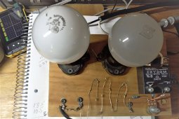
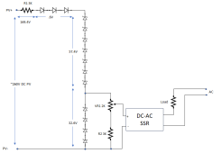
Everyone wants simple diversion and this uses cheap zeners, diodes and an AC solid state relay. This is a way to divert or turn on a water heater only when there is excess power based on array voltage going over expected power point. Instead of timers, use this as a way to prevent water heater from turning on while batteries are still charging.
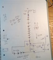
I used 1N756 500mw 8.2V zeners as a way to build up offset voltage. 20 of these were only $3 shipped from US. Additional voltage offset is using the forward voltage of 0.6V to fine tune. Four zeners prevent the voltage from exceeding the 32V input voltage of AC brick.
The solid state relay is a very non linear load which doesn't conduct till the LED reaches on voltage. Then an internal circuit makes the load constant current. That will be about 2ma from 3V to 32V. That makes it difficult to use a potentiometer to adjust the voltage over a wide range. That is a bonus because the resistors will always see limited current and not have to dissipate a lot of heat. This is very simple to correct if a FET or TL431 is added to circuit making it more complex. Stack as many zeners as you want to get near array voltage then use any silicon diode forward voltage drop to make finer adjustments . Later, I will show will show how an old MSW inverter can be easily modified to operate on any voltage array and divert directly from panels. On a 48V system the turn on and off is close enough to allow diversion based on battery voltage.
These SSR have a fairly sharp turn on at about 2.2 to about 2.4V. This is for positive half cycle turn on. You have to get to 2.7V to about 2.9V before both positive and negative cycles turn on. This may irritate some lower powered sine wave inverters. A MSW inverter won't care. Again, this is simple and cheap


