diy solar

diy solar

Single cell voltage drop for no apparent reason

Philtao

Sailor, EE & Designer of the TAO BMS
Joined
Jun 10, 2021
Messages
43
Location
Australia
Hi,
On my boat I have a 600Ah DIY 12V bank with Winston cells installed 6.5 years ago (cells with sequential serial numbers).
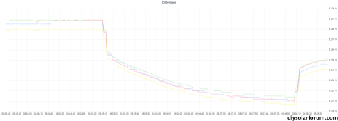
The cells are well top balanced and yesterday the voltage for one of the cells dropped suddenly by more than 100mV compared to the other cells... then later came back to same level as other cells. I cannot think of any reason to explain that behaviour, so I welcome any hypothesis.

See attached cell voltage and current graphs showing the weird voltage drop... and recovery
Cell #4 is the top of stack cell

Sequence of events:
  • 05:30 - all cell voltages are within a 3 mV range when the engine is started and the battery starts charging
  • 05:40 - voltage for cell #4 starts to drop compared to the other cells
  • 05:47 - sails are up and engine is stopped = no more charge -> voltage for cell #4 continues to drop compared to other cells
  • 07:00 - wind dies and engine is started -> cell #4 voltage keeps drifting apart from other cells
  • 07:37 - BMS triggers the alarm for cell voltage differential (set at 100 mV difference between cells)
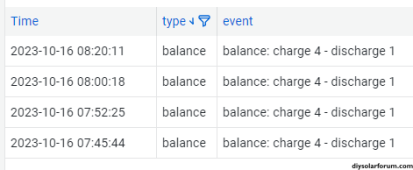
  • 07:45 - I lower the minimum cell voltage to enable balancing (was 3.4V, down to 3.35V) and the BMS initiates balancing to charge cell #4 and discharge cell #1 with 2A current (while battery charge current is above 40A) -> instantly cell #4 voltage jumps up to be within a few millivolts of other cells voltage
I have seen the same thing happen a few months ago. I disconnected, inspected, cleaned, greased and reconnected all the links between cells and all has been fine since (so I know the contacts on the cells terminals are good).

All cell voltages are measured by a single Analog Digital Converter so I exclude a possible error in the measure.

The cell resistances measured by the BMS are very stable over time and within a 0.04 mOhm range:
  • cell #1: 0.26 mOhm
  • cell #2: 0.26 mOhm
  • cell #3: 0.24 mOhm
  • cell #4: 0.28 mOhm
I noticed that when balancing is required it is always cell #4 that needs to be charged so I guess it must have aged faster than the other cells. But that cannot explain sudden voltage drop and recovery!
 

Attachments

  • 231016_voltage_drop.pdf
    159 KB · Views: 7
Hi,
On my boat I have a 600Ah DIY 12V bank with Winston cells installed 6.5 years ago (cells with sequential serial numbers).
The cells are well top balanced and yesterday the voltage for one of the cells dropped suddenly by more than 100mV compared to the other cells... then later came back to same level as other cells. I cannot think of any reason to explain that behaviour, so I welcome any hypothesis.

See attached cell voltage and current graphs showing the weird voltage drop... and recovery
Cell #4 is the top of stack cell

Sequence of events:
  • 05:30 - all cell voltages are within a 3 mV range when the engine is started and the battery starts charging
  • 05:40 - voltage for cell #4 starts to drop compared to the other cells
  • 05:47 - sails are up and engine is stopped = no more charge -> voltage for cell #4 continues to drop compared to other cells
  • 07:00 - wind dies and engine is started -> cell #4 voltage keeps drifting apart from other cells
  • 07:37 - BMS triggers the alarm for cell voltage differential (set at 100 mV difference between cells)
  • 07:45 - I lower the minimum cell voltage to enable balancing (was 3.4V, down to 3.35V) and the BMS initiates balancing to charge cell #4 and discharge cell #1 with 2A current (while battery charge current is above 40A) -> instantly cell #4 voltage jumps up to be within a few millivolts of other cells voltage

What BMS?


I have seen the same thing happen a few months ago. I disconnected, inspected, cleaned, greased and reconnected all the links between cells and all has been fine since (so I know the contacts on the cells terminals are good).

So, you're saying you saw it before... you inspected and cleaned connections, it resolved it, but for some reason, you think the issue can't return? Actually, this suggests that since the activity corrected the condition, the condition has repeated just as much is it gives confidence in quality of the connections.

It also suggests that in the past, you have confirmed erratic voltage behavior is related to a sensing issue.

All cell voltages are measured by a single Analog Digital Converter so I exclude a possible error in the measure.

It's unclear if the analog digital converter is in addition to the BMS. If so, are you saying the cell voltage drop has been confirmed via a separate measurement? Is there any commonality between A2D sense and BMS balance wires? If so, have you tried confirming it with a simple voltmeter?

The cell resistances measured by the BMS are very stable over time and within a 0.04 mOhm range:
  • cell #1: 0.26 mOhm
  • cell #2: 0.26 mOhm
  • cell #3: 0.24 mOhm
  • cell #4: 0.28 mOhm
I noticed that when balancing is required it is always cell #4 that needs to be charged so I guess it must have aged faster than the other cells. But that cannot explain sudden voltage drop and recovery!

You either have a sensing issue, or you have a failing cell. I see no evidence that you can exclude either.
 
Last edited:
I’d still be leaning towards a bad connection. Clean is not the same as no oxide on the terminal. Clean the contact surfaces with acetone to remove any grease shine it up evenly, by hand with Scotch bright, wipe off debris. Only a light buff on busses or lugs as to not remove too much tin or nickel plating. Use non metal containing anti oxidant like No-ox-id A special, marine green grease (winch grease) or silicone dielectric grease on the contact surface. No zinc, copper, silver or carbon paste. Don’t forget to service the pos & neg lugs too.
 
Thanks @sunshine_eggo and @Skypower for your suggestions - that helps me in my thinking... and come to a conclusion.
I use the BMS I have designed and sell: the TAO BMS

So, you're saying you saw it before... you inspected and cleaned connections, it resolved it, but for some reason, you think the issue can't return? Actually, this suggests that since the activity corrected the condition, the condition has repeated just as much is it gives confidence in quality of the cell terminals.
The condition corrected by itself before I cleaned the connections. I cleaned the connections as, at that time, I did not think of other possible causes and because I never did it since the battery was installed (6.5 years).

It also suggests that in the past, you have confirmed erratic voltage behavior is related to a sensing issue.
No I have never had sensing issues or erratic voltages

It's unclear if the analog digital converter is in addition to the BMS. If so, are you saying the cell voltage drop has been confirmed via a separate measurement?
The ADC is part of the BMS. No the voltage drop has not been confirmed by a separate instrument, but it is the same instrument (ADC) measuring all cell voltages - and it seems that other voltages are correct.

Is there any commonality between A2D sense and BMS balance wires? If so, have you tried confirming it with a simple voltmeter?
Yes they are the same wires, but balancing is suspended while a voltage measure is taking place. There was no balancing activity when the condition appeared and it was when a balancing cycle was initiated that the condition disappeared (each balancing cycle is set to 120 seconds followed by a 15 seconds delay before deciding if more balancing is required).
1697519314760.png
I did not have the chance to confirm with a voltmeter this time (but I did the first time it happened - and measures were spot on within 2 mV)

You either have a sensing issue, or you have a failing cell. I see no evidence that you can exclude either.
I am fairly confident that it is not a sensing issue as not a single issue has been reported for the last 3 years on 70 installed BMS. Also the BMS has built-in self diagnostics that run every hour to validate the cell voltage measure chain with a reference voltage.

Unfortunately you must be right... and that leaves me with a failing cell! I can only think of a drop in cell internal resistance to explain the measured voltage, then suddenly return to normal (like a "bubble" that grows then pops and disappear). My understanding is that most often a failing cell would have an increased internal resistance. Also, how is it the voltage difference between cells is not proportional to current?
There must still be some mystery about the internal chemistry of lithium cells over time. I will have to wait for the next time it happens...
I’d still be leaning towards a bad connection. Clean is not the same as no oxide on the terminal. Clean the contact surfaces with acetone to remove any grease shine it up evenly, by hand with Scotch bright, wipe off debris. Only a light buff on busses or lugs as to not remove too much tin or nickel plating. Use non metal containing anti oxidant like No-ox-id A special, marine green grease (winch grease) or silicone dielectric grease on the contact surface. No zinc, copper, silver or carbon paste. Don’t forget to service the pos & neg lugs too.
That was also my thinking when it first occurred as the voltage being measured is the difference between the positive post of the previous cell and the positive post of the current cell - therefore taking into account one cell link (2 connections).
But now that I did a bit more thinking and concluded that the voltage drop means there is a drop in internal resistance I can hardly imagine the connections' resistance getting lower progressively than returning suddenly to what it was within a few minutes. It sounds more like an electro-chemical phenomenon (?)
Thanks for your advice on the proper way to clean connections. I use Corrosion-X to protect the connections (and everything electrical on the boat as well as all metal and plastic). It is dielectric and leaves only a microscopic layer that does not prevent electrical contact. It has been working for me but, as you seem to know what you are talking about, any feedback you may have about that product is welcome. Before that I was using a silicone dielectric grease sold for that purpose.
 
as above plus look for corrosion in the BMS sense cables themselves, you could have corrosion under the plastic coating and not know it.
Thanks for the suggestion. I have plenty of sense wires in stock so I will replace with a new one.
 
Swap the cell positions to verify a cell or a sensing issue.

Dendrites short and fuse if there is plating, can your BMS measure IR under load? If so put the pack under full load and see if that cell has higher IR.
 
Swap the cell positions to verify a cell or a sensing issue.
Good idea... but that is a lot of work getting the battery out from where it is in the boat. Will do it tomorrow.
Dendrites short and fuse if there is plating, can your BMS measure IR under load? If so put the pack under full load and see if that cell has higher IR.
The first 3 years for that battery was in the tropics (> 30°C) with a very basic BMS that did not control the chargers to stop charge at lower SOC . So I guess there must be some plating.

Not sure what "under load" means. The BMS detects suitable changes in current over very short time frame while SOC is within a suitable range and calculates IR = "delta V" / "delta I".
If that is not what you mean, do you have any reference on how to measure resistance "under load"?
 
Last edited:
How that cell is behaving is not how I would have imagined it. You would think it would let go and the problem area within would escalate, not heal like a troublesome semiconductor. Dropping down then coming back like nothing happened, just plain weird? I got my fingers crossed that it’s an external issue, connection/component. I have no experience with Corrosion X. They make bold claims most of I like to believe. The main job of an antioxidant as to our terminals is to keep moisture out and stay there(not migrate or wick away). It also has to be inert to the dissimilar metals while current passes. I’ve been surprised by how bad some products are, some actually making things worse and would have been better off without it. Your situation, hot humid, salty air, I can imagine a better test condition. Hopefully its something cheap and simple.
 
Good idea... but that is a lot of work getting the battery out from where it is in the boat. Will do it tomorrow.

The first 3 years for that battery was in the tropics (> 30°C) with a very basic BMS that did not control the chargers to stop charge at lower SOC . So I guess there must be some plating.

Not sure what "under load" means. The BMS detects suitable changes in current over very short time frame while SOC is within a suitable range and calculates IR = "delta V" / "delta I".
If that is not what you mean, do you have any reference on how to measure resistance "under load"?
That will indicate if a cell is degraded. Just put the maximum load you can on the battery and see if the suspect cell has a higher IR under that load.

When Winston cells first became easily available there was a guy in Queensland installing a lot of systems, he was allowing the cells to stay at high voltage and high temperature and a lot of systems failed within a few years. I saw an scan of a cell and you could see the dendrite fuses that had taken out parts of the cell. The characteristic of a failing cell was voltage sag under load.
 
Just put the maximum load you can on the battery and see if the suspect cell has a higher IR under that load.
Max load is the boiler with 110A load. All cells react the same way.
Before load: 8.35 A charge - cell voltage from 3.280V to 3.289V (9 mV range)
3.5 seconds after applying 106 A load: cell voltage from 3.252V to 3.259V (7 mV range)
Which approximate the cell IR between 0.245 and 0.262 mOhm (which seems acceptable after 6.5 years for cells given with a nominal IR = 0.25 mOhm)1697580644996.png
Suspect cell #4 is red (legend overwritten by diysolarforum.com)

When Winston cells first became easily available there was a guy in Queensland installing a lot of systems, he was allowing the cells to stay at high voltage and high temperature and a lot of systems failed within a few years. I saw an scan of a cell and you could see the dendrite fuses that had taken out parts of the cell.
What I observed are probably the first symptoms of these dendrite fuses that could be unstable as they develop and create erratic readings.
Thank for your input and I start saving for when the battery gets worse and I need to replace it :(
 
That will indicate if a cell is degraded. Just put the maximum load you can on the battery and see if the suspect cell has a higher IR under that load.

When Winston cells first became easily available there was a guy in Queensland installing a lot of systems, he was allowing the cells to stay at high voltage and high temperature and a lot of systems failed within a few years. I saw an scan of a cell and you could see the dendrite fuses that had taken out parts of the cell. The characteristic of a failing cell was voltage sag under load.
Do symptoms of dendrites come and go? Or is it easily repeated with voltage sag under load?

His recent “test” showed all cells behaved as should with nothing of note.

My gut is sensing/reporting of the BMS.

Easiest way is to capture another event and measure with a DMM. Then you can verify if the BMS is just reporting abnormal voltage readings.
 
Easiest way is to capture another event and measure with a DMM.
I did that on the first occurrence (a few months ago) and DMM reading were the same as reported by the BMS... but I did not record the measures in my log book :(
If it happens again that will be the first thing I do and record data for reference.
 
What BMS?

:ROFLMAO:

1697587415427.png
I noticed that when balancing is required it is always cell #4 that needs to be charged so I guess it must have aged faster than the other cells. But that cannot explain sudden voltage drop and recovery!

The likely suspects are a cell with self-discharge issues, a poor connection resulting in erroneous readings, and a BMS that screws up balancing.

Can you suppress balancing while keeping over/under voltage protection for the cells?
Your DIY BMS of course has to be the first thing to consider.

You say it got better for a while after cleaning and re-making contacts. While charging or discharging at higher current, measure the mV drop from cell terminal to next cell terminal connected by busbar (nominally 0.000V), and if any outliers, check which interface has the excessive voltage drop.

You checked voltages once, check again at the cells, bypassing all sense lines.

What environment does your BMS PCB experience?
How well cleaned was it? I've experienced 30 Meg ohm leakage on a power supply sense circuit (24V and resistive dividers) that was assembled with "no clean" flux. Weather in San Jose affected it. A nice isopropyl alcohol bath cured it.


Swapping cell positions in the pack is another test.
 
Should it happen again, use a DVM and get a reading at the cell’s big glued in hex nuts since you can’t get at the actual terminal tops that’s occupied by the busses. If you are getting the same results as the busses you’ll know that it’s not a bad connection.
If that’s the case, then you may have to make arrangements for the good soldier, Mr Winston.
 
Last edited:
I would be inclined to go with a poor connection rather than a bad Cell. Usually defective Cells are not like a light bulb and turn on or off. Defective Cells are just that defective and can be tested for load and capacity and verified that they are indeed defective.

If you have any doubt about Cell number 4 then pull the Cell and test it.

I would clean the connections with scotchbrite. Apply a dielectric grease to the contact, get a torque wrench and torque each of the bolts to spec.and you should be good to go.
 
Max load is the boiler with 110A load. All cells react the same way.
Before load: 8.35 A charge - cell voltage from 3.280V to 3.289V (9 mV range)
3.5 seconds after applying 106 A load: cell voltage from 3.252V to 3.259V (7 mV range)
Which approximate the cell IR between 0.245 and 0.262 mOhm (which seems acceptable after 6.5 years for cells given with a nominal IR = 0.25 mOhm)View attachment 172754
Suspect cell #4 is red (legend overwritten by diysolarforum.com)


What I observed are probably the first symptoms of these dendrite fuses that could be unstable as they develop and create erratic readings.
Thank for your input and I start saving for when the battery gets worse and I need to replace it :(
I doubt it’s the cell given that data - the cells I’ve experienced that have experienced dendrite fusing all have reduced capacity and higher IR under load.
 
Can you suppress balancing while keeping over/under voltage protection for the cells?
Yes balancing is independent from the BMS protection and energy management functions. But when the event occurred the cell voltage was too low to allow balancing.
While charging or discharging at higher current, measure the mV drop from cell terminal to next cell terminal connected by busbar (nominally 0.000V), and if any outliers, check which interface has the excessive voltage drop.
Just did that with 110 A load. Measured from cell terminal top to cell terminal top using a Blue Sea multimeter (1mV is the limit of what it can measure!).
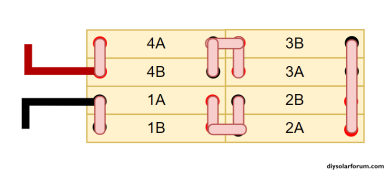
Here is my 2P4S cell configuration:
1697591209668.png
Links between cells in parallel are the ones supplied by Winston and are placed against cell terminals
Links between cells in series are copper bars placed above the Winston links
Connection from 2A to 3B is a single copper bar (no Winston links)
M12 bolts

Measures:
1B - 2A = 2mV (R = 18 µOhm - 0.22W dissipated)
2B - 3A = 1mV (R = 9 µOhm - 0.11W dissipated)
3B - 4A = 2mV (R = 18 µOhm - 0.22W dissipated)

It sounds logical that connections 1B-2A and 3B-4A have twice the resistance of connection 2B-3A as there are twice the number of contacts (terminal B - Winston link - copper bar - Winston link - terminal A compared to terminal B - Winston link - terminal A).
Although the measures are not precise due to being at the limit of the DMM specs, it appears that contact resistances are the same for all connections = 4.5 µOhm.
A quick look on Internet shows that this a good / acceptable contact resistance:

I did the same measure 5 minutes later and values were twice what I initially measured! Temperature must ave something to do with it: reduced bolt pressure? (pity my infrared thermometer just died)

What environment does your BMS PCB experience?
PCB are manufactured in a factory and have a conformal coating. Although being on a boat the environment is dry with no visible corrosion observed on any surrounding metal.
All contacts (sense wires, fuses...) and bare metal are coated with CorrosionX
 
Thank you all for your input.
So after all my cells may not be as bad as I thought :)

I'll keep investigating on the cell connection side... if / when the event happens again. I will measure cell voltage at the terminals as well as the terminal temperature. Then I will clean and redo the connections as suggested by many of you... and see if it happens again.
 
Low resistance measurements sound good. you had three figures, there are two more where cables connect.

Didn't realize you had 2p4s. (I'm a visual guy, and 600 Ah didn't click)

2x the resistance, 2 cells paralleled, half the connections remained good?

When ratios like 2:1 appear we can be talking about single electrons or photons (in other fields), not in this case of course ;)

Not sure if intermittent involving the 2p could explain the voltage shifts you see for float, could for charge/discharge voltages.

Disconnecting half the cells so it is just 4s, any faults would readily become apparent.
But it is the connections I'm suspecting, and you'll be messing with them, leaving uncertainty. (Thanks, Heisenberg!)

Conformal coat certainly helps. "Factory"? I've had the hardest time getting them, or guys I worked with to support me, in doing what I want. They had a Trident (dishwasher for PCBs) and weren't afraid to use it. With "Saponification agents" (makes soap out of grease, basically draino?) Solder flux remained. Longer time than manufacturer recommends, flux was mostly gone but metal leads were discolored.

IPA worked for me. I recommended a Kyzen product based on IPA, with additives, made for the job. But never got my way. https://kyzen.com/industries-applications/electronics-assembly-cleaning/pcb-cleaning/

At my new job I've suggested interdigitated test patterns which could be Hypotted during environmental tests, to expose if any residue remains that could cause leakage.
 
Back
Top