diy solar

diy solar

Sol-Ark 15k Current Capabilities

62.5A is the Inverter limit (DC-> AC).
The 50A is based upon 275A at a minimum battery voltage. I routinely push 14,000 watts (58 amps) off the battery. In fact, if you build a 17s battery, you can push the full 62.5A with a 54.6v battery.
I believe when the Sol-Ark is off, it passes through Grid Power. It is possible that certain failures would take you off grid.
So you routinely run 7000 watts per leg? For how long? Surge or no surge?
 
That 160A limitation when you have a single battery input is definitely something to keep in mind! There are Y jumpers available (I believe Homegrid actually makes them) that will parallel those battery positive inputs if you need to run a single cable into the 15K. Although with a single cable you want to be sure it is heavy enough for that 275A current! Often the lug crimp is actually where you start getting heated up, so always be sure to have a proper crimp!

We came to the realization of that single positive input bottleneck when we popped the DC battery breakers from solar production on our one job! 🤪 I should have thought about it.... 200A x 80% continuous = 160A. But the job started out with a lot less panels and loads, and then as "things" (loads, solar, batteries) got added I forgot.... That job was 3 hours from the shop. :fp2 Service call, here we come. Lol.
 
160a is only if you have one of the battery connections. When you have both battery connections, the limit is 275a.
Correct. I have two EG4 power pro 14.3 Kwh batts and they are almost perfectly built to hook up to the Sol-Ark 15 in that you run one (each - pos/neg) 2/0 cable with Amphenol style connectors to each battery to parallel the batteries and then two Amphenol style to ring connectors (two pos and two neg) from the "master" battery to the two inputs on the Sol-Ark so you can get the full 275a if you every need to.
 
That 160A limitation when you have a single battery input is definitely something to keep in mind! There are Y jumpers available (I believe Homegrid actually makes them) that will parallel those battery positive inputs if you need to run a single cable into the 15K. Although with a single cable you want to be sure it is heavy enough for that 275A current! Often the lug crimp is actually where you start getting heated up, so always be sure to have a proper crimp!

We came to the realization of that single positive input bottleneck when we popped the DC battery breakers from solar production on our one job! 🤪 I should have thought about it.... 200A x 80% continuous = 160A. But the job started out with a lot less panels and loads, and then as "things" (loads, solar, batteries) got added I forgot.... That job was 3 hours from the shop. :fp2 Service call, here we come. Lol.
I had the same question and got an excellent response from Shaun at Sol-Ark:
The 15K-2P-N reaches a max battery charge/discharge of 275A if using both sets of battery terminals.
If only one set of terminals is used, the max battery charge/discharge will be limited to 160A.

If you have x2 (#2/0 AWG) cable pairs from the battery bank busbars, then yes! Hook ++ cables to the two positive terminals on the inverter, and -- cables to the negative terminals.

275A is too large for a single terminal post, since each post is rated for 160A, and #4/0AWG Cable is not rated up to 275A, so the correct way to IS to use both terminal posts and #2/0.

If each battery has it's own pair of cables (+ & -) but the batteries are NOT combined to busbars (++ & --) then you should probably terminate each battery cable at a busbar for ++ and a separate busbar for -- and then have a pair of #2/0AWG conductors from each busbar to each corresponding battery terminal at the inverter. This is a "best practice" to ensure even power distribution and battery exercise (and to avoid developing imbalance issues over time).

For connecting a single #4/0 AWG cable to the inverter posts you would use a terminal busbar:
1708553954391.png
x2 (#2/0 AWG) Conductors: <380A @<90°F thin-strand copper
x1 (#4/0 AWG) Conductors: <260A @<90°F thin-strand copper

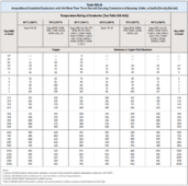
Check your planned Wire Ampacity:

1708553954505.png
 
I had the same question and got an excellent response from Shaun at Sol-Ark:
The 15K-2P-N reaches a max battery charge/discharge of 275A if using both sets of battery terminals.
If only one set of terminals is used, the max battery charge/discharge will be limited to 160A.

If you have x2 (#2/0 AWG) cable pairs from the battery bank busbars, then yes! Hook ++ cables to the two positive terminals on the inverter, and -- cables to the negative terminals.

275A is too large for a single terminal post, since each post is rated for 160A, and #4/0AWG Cable is not rated up to 275A, so the correct way to IS to use both terminal posts and #2/0.

If each battery has it's own pair of cables (+ & -) but the batteries are NOT combined to busbars (++ & --) then you should probably terminate each battery cable at a busbar for ++ and a separate busbar for -- and then have a pair of #2/0AWG conductors from each busbar to each corresponding battery terminal at the inverter. This is a "best practice" to ensure even power distribution and battery exercise (and to avoid developing imbalance issues over time).

For connecting a single #4/0 AWG cable to the inverter posts you would use a terminal busbar:
View attachment 197421
x2 (#2/0 AWG) Conductors: <380A @<90°F thin-strand copper
x1 (#4/0 AWG) Conductors: <260A @<90°F thin-strand copper

Check your planned Wire Ampacity:

View attachment 197422
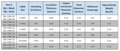
The WindyNation 4/0 that I use is rated for much higher than your chart says.

1708555300332.png

Also with a voltage drop calculator is only a 0.17% of voltage drop for 3ft at 275a and 48v.

I don't think 2x 2/0 cables is REQUIRED. But definitely doesn't hurt.
 
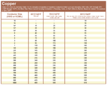
Most generic charts ive referred to emulate this or at least very close
IMG_2134.png
 
Does 4/0 cable fit the terminals? I might have extra laying around.
I believe they are 3/8 in lugs so if you had a 4/0 terminal with a 3/8 in hole it would work but you would still need two to hook up to both of the inputs (actually four, two + and two - ) if you wanted to get the max 275 amp rating
 
I believe they are 3/8 in lugs so if you had a 4/0 terminal with a 3/8 in hole it would work but you would still need two to hook up to both of the inputs (actually four, two + and two - ) if you wanted to get the max 275 amp rating
Oh, it has lugs, that helps. (y)

Yes, I understand the limitations with using single cables and not pairs.
 
One other thing to remember is that if you have your cables in free air, that makes a difference on ampacity rating as well, if I'm not mistaken.

For instance, the chart listed by @niccolosartor specifically says at the top "in raceway, cable or earth".

I believe a lot of those ratings have to do with heat buildup when the wires/ cables are inside a conduit or raceway. Most of the systems that we install have the cables in free air for the most part. We usually use welding cable as that is relatively easy to work with because of the thin stands of wire.
 
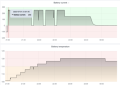
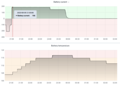
I did have heat/temp issues with 275A in the summer using a 38kWh Homegrid battery when charging from grid full blast (I get free grid power at night so I charge from grid every night). I dialed down the charge rate a bit and it's been fine since.

You can see the dropouts in charging as the battery temp was getting over 115F.

1708609093055.png

I have reduced the charging power to 10kW and it stopped happening.

1708609274156.png

Can't tell if it was Sol-Ark or Homegrid doing the cutting.
 
I did have heat/temp issues with 275A in the summer using a 38kWh Homegrid battery when charging from grid full blast (I get free grid power at night so I charge from grid every night). I dialed down the charge rate a bit and it's been fine since.

You can see the dropouts in charging as the battery temp was getting over 115F.

View attachment 197560

I have reduced the charging power to 10kW and it stopped happening.

View attachment 197561

Can't tell if it was Sol-Ark or Homegrid doing the cutting.
Interesting. I'm assuming you have the Homegrid's in closed loop connetion?

I have seen warning/error codes on the "Lithium" tab in the Sol-Ark, have you checked there when its happening?

Do you know the inverter temp when it dropped out?
 
Correct, Homegrid is connected via CAN-BUS.

Inverter temp appears to be around 66C when the dropouts happen (Had to look in the sol-ark data, Solar assistant still fails to capture temp data for Sol-Ark 15K)
 
Correct, Homegrid is connected via CAN-BUS.

Inverter temp appears to be around 66C when the dropouts happen (Had to look in the sol-ark data, Solar assistant still fails to capture temp data for Sol-Ark 15K)
Ah thats right, SolarAssistant only looks at DC temp, which there is no DC temp sensor in the 15k, so it reads an erroneous value from a resistor.

The thermal cutoff is well well above 66C, so its definitely the battery cutting back power because of high temps. Very cool to see that happen though!
 
I did have heat/temp issues with 275A in the summer using a 38kWh Homegrid battery when charging from grid full blast (I get free grid power at night so I charge from grid every night). I dialed down the charge rate a bit and it's been fine since.

You can see the dropouts in charging as the battery temp was getting over 115F.

I have reduced the charging power to 10kW and it stopped happening.

Can't tell if it was Sol-Ark or Homegrid doing the cutting.
Looks like you didn't quite hit 50C / 122F when the battery high temp protection should activate - killing charging and throwing a code 6 on the display. Or maybe you did...it's close.

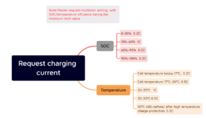
At the temps listed it should have derated to no lower than 0.2C (160A on your setup) - not full up killed charging (see attached that HomeGrid support provided me when I bugged them).

Then again that chart hasn't held very true in my experience.

Might be one of the other three sensors the system monitors and can error out when in high temps:
Code 11 - Ambient High Temp Protection
Code 22 - Relay Over Temp Protection
Code 23 - Copper Bus Bar Over Temp Protection

I've had my setup drop out once last summer with a Code 22 while grid charging at upwards of 530A / 27.3 kW in the afternoon. I don't remember what the temp was in the garage but the previous day was a 113F high. Indicated battery temp during the drop was 41C / 106F. Less than 5 minutes later it cleared the code and allowed charging again.
 

Attachments

  • Homegrid Charge Request Logic.png
    Homegrid Charge Request Logic.png
    133.9 KB · Views: 5
Last edited:
Looks like you didn't quite hit 50C / 122F when the battery high temp protection should activate - killing charging and throwing a code 6 on the display. Or maybe you did...it's close.

At the temps listed it should have derated to no lower than 0.2C (160A on your setup) - not full up killed charging (see attached that HomeGrid support provided me when I bugged them).

Then again that chart hasn't held very true in my experience.

Might be one of the other three sensors the system monitors and can error out when in high temps:
Code 11 - Ambient High Temp Protection
Code 22 - Relay Over Temp Protection
Code 23 - Copper Bus Bar Over Temp Protection

I've had my setup drop out once last summer with a Code 22 while grid charging at upwards of 530A / 27.3 kW in the afternoon. I don't remember what the temp was in the garage but the previous day was a 113F high. Indicated battery temp during the drop was 41C / 106F. Less than 5 minutes later it cleared the code and allowed charging again.
He could have had 1 battery hit the 122*F, and the solar assistant is just taking an average of all the packs?
 
Mind you, I'm in TX and we had outside temps well into 100+ during this time and the garage, while insulated, was probably pretty toasty.
 
He could have had 1 battery hit the 122*F, and the solar assistant is just taking an average of all the packs?
Yeah...I was thinking that. While the HomeGrid BMS only relays one temp signal to the Sol-Ark the HomeGrid BMS could decide to throttle charging based on individual cell/slab temps even though the average across the array doesn't look too bad.
 
Yeah...I was thinking that. While the HomeGrid BMS only relays one temp signal to the Sol-Ark the HomeGrid BMS could decide to throttle charging based on individual cell/slab temps even though the average across the array doesn't look too bad.
I wonder why its not throttling, and its just killing charge current all together?
 
Back
Top