diy solar

diy solar

Solar array ground mount ballast.

Jack Rabbit Off Grid

Solar Enthusiast
Joined
Sep 6, 2021
Messages
477
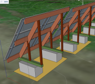
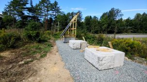
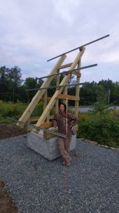
I’ve been planning my PV array ground mount for about a month. I started trying to auger holes for posts with a 1600# tractor. That failed miserably! The ground is so rocky it will never happen. So my next plan it to just put concrete feet on the bottom of the 6 legs made of 4x6” pressure treated posts. 3 of them will be the tall legs and have 2 foot tall by 16” diameter feet holding 6.19 60# bags and the shorter side of the frame will have 3 1 foot tall by 16” diameter feet holding 3.1 60# bags. Total ballast will be 1,671#. The surface area of the panels in portrait mounting will be 11’6” from top to bottom and 17’1” wide With a 40 degree tilt. So about 196 square foot of wind sail.

1,671lbs going to be enough? I already have the 16” SonoTube but not enough to make 6 2 foot tall feet that’s why I want 3 tall and 3 short Feet.

Also pouring a solid slab is out of the question. The ground is uneven and getting a large piece of heavy equipment to level it is not really possible.

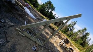
something like this but made from 4x6’s and 2x6’s bolted together.
730497B5-3B2A-4E27-8B61-BD78AF1889CF.png
 
Ballast requirements are different for each jurisdiction. Check your local code enforcement.
 
I didn’t know that. I’ll see if I can find it.

thank you.
Its can also a matter of soil makeup if you bury the ballast in the ground. That's what I did.
There are 4 classes ranging from sand (loosest) to xx (hardest). Some jurisdictions want to 'test the soil' to determine the class and therefore the size of the ballast required. So I just did the worst / largest ballast so that incase I have to actually get inspected some day it won't fail because my ballast was too small.

I used the IronRidge design tool - it shows you hole size and depth for classes of soil. You can do narrower and deeper or wider and less deep. In my case I went widest / less deep because I dug it by hand - e.g. like 24" wide and 36" deep. This took 25 x 60lbs bags of concrete for each hole :)

You can find the tool at https://www.ironridge.com/design-tools/
Here's an example of parameters you can play with and get guidance on hold/ballast size.
1646102921946.png
 
Last edited:
I’m mounting 9 or 12 295 watt panels on these concrete pads 3’ x 6’6 by 8” thick
I’m on Solid rock and can’t dig .
2B2C919E-2BE3-4246-8C07-FD6C60E2CB9A.jpeg
 
I’m mounting 9 or 12 295 watt panels on these concrete pads 3’ x 6’6 by 8” thick
I’m on Solid rock and can’t dig .
OK, then maybe take a look at @DavidPoz's arrays - they are metal frames with surface ballast and some anchors - as an actual implementation that works for him.

Here's an example of the first array - held with surface ballast

This is another array he did later on with used surface ballast + anchors.
 
Will contribute to this thread as I am in the middle of designing our 100% above ground ballast mounting system (hopefully as cheaply as possible)

Open to ideas / suggestions ... and I can mock stuff up as requested to verify thoughts.

Naming the parts:
The block seen here is a retaining wall precast block, 24x24x48, 2800 lbs corner block with smooth top.
Wood is 4x4's and 2x10's PT GC (all pieces standard sizes of 8-10-12ft)
Channel is 12ga superstrut
All wood to be bolted to blocks with 5 piece expansion bolts.
All wood joints to be made with gusset material typically found on trusses, backed up with nails.
PV Panels shown are bifacial.

Design considerations:
No zoning up here. We do live in an area with 70lbs ground snow loads, and 110 winds so far as insurance is concerned.
Front of panel face 3ft off ground by design
55 degree angle to maximize winter output and smooth out summer numbers
Similar sized system, 18 panels, is $3500 in steel without the concrete ... ideally this is much cheaper and just as strong
System needs to be above ground, we have shallow ledge and cannot dig footers. (Though I did debate driving rebar into ledge and pouring ballast on top of ledge)

V1: based on surface area calculations for this option 110mph winds exert something like 3400 lbs of force at this angle (55 degrees)
What is nice about this though is it is a single block, and if frost heave is an issue the units will move as one and not affect the other panels in the array.

I believe for this design to "work" for high winds it needs two blocks.

image (20).png

V1.2: Same idea but one solid array of 18
image (21).png

V2: two blocks, replace 2x10's with 4x4's, add an extra vertical support. Should withstand wind but unit might be affected by frost heave
image (22).png

V3: again two blocks but removing center vertical support from V2
image (23).png
 
If you are on bedrock there won't be frost heave.
I have an engineered ballast system 32 415w panels.
Print says 4 ballast blocks 30"*12"*120".
I did some super sophisticated ? back of napkin wind load calcs and will probably be increasing the ballast blocks by about a third.
If it's worth doing, it's worth overdoing!
 
If you are on bedrock there won't be frost heave.

Even if there is soil above said ledge? The area I am putting this isn't flat, but sloped. Water here flows along the ledge from an uphill wetland, this makes things "fun" in spring when stuff starts to thaw as I haven't "fixed" our dirt road yet to allow for this extra water.

The first step I was going to take was to make the area I want to put these panels flatish ... which likely means building up vs going down (something I have a lot of experience with having built a foundation last year)
If there is soil in between your ballast and bedrock then you aren't "on bedrock" ?
Big excavator came in and made a flat spot for me to build on.
 
I haven't brought our backhoe over there to confirm depth of ledge yet.

If I were to pin to the ledge for footers ... and if I do can I get away with any of the designs above given the ledge isn't going anywhere? lol

I wonder how big I would need to make the footers that way ...
 
So here is what I am thinking. (see attached)

Key:
Green: PT 6x6
DkBrn: 4x4 ... maybe 4x6
LtBrn: 2x10 (headers are 2 of them together to make a 4x10)
BlGray: 1.5x1.5 Unitrack or equivalent
LtGray: 2x2x4ft concrete blocks, 2840 lbs each.
Yellow: 4-6" of 3/4 stone on top ground

Thoughts: (check me on this)
* I calculated wind loads ... these blocks should be fine BUT as a backup for the backup I will likely tie them down with something like duck bill anchors OR simply rebar driven into the ground / ledge and secured to the blocks via wire. The design here has 2 less panels which brings the wind loads down to below the block weight ... levering actions asside.

* I will use the same wire to cross brace the back ends for racking issues ...
* I was thinking of notching out where the unitrack will go for each rail to make mounting with a bolt easier ... likely forsner bit the back flat?
*For mounting the 4x4 (or 6) to the 6x6 I was thinking of using plate steel, painted, with some type of barrier between it and the wood surface, then bolting through the wood into the concrete via embedded 1/2 threaded rod (for center) or in the case where there is no concrete to mount to simply bolting it together with 1/2 hardware.
* 6x6 will be secured to block with at least 4 embedded 1/2 threaded rods
* there will by 6 panels per "unit" and the units will not be connected to each other ... in the off chance there are frost issues the units would move independently from each other.
* separation of units will be 1ft ... this would allow for 5 degrees of movement ... which is a total of 1.5ft of vertical lift (which is crazy to think about)
* I haven't decided on how to mount the headers to the 4x4 (or 6)'s yet ... If I went with 6's then I could use two lag bolts offset at an angle and extend the 4x6's vertically 10" from where they are shown here. I think this is likely the way to go. If I use 4x4's then I would do two lag bolts centered OR get a 4x4 header mount with one bolt through each member.

Current project status:
* I dug the trench the other day from solar location to first out building and ordered the wire (0/1-0/1-2 URD) to go in it.
* validated site location in sketchup using my photogrametic image of the site to confirm shadows on this first array.
* Ordered the 8 blocks to be made
* Already own the unitrack and mounting hardware / solar etc.
* This weekend I will start clearing the area these are going and putting down some stone and maybe picking up the blocks.
* No wood or hardware for this has been acquired yet.
 

Attachments

  • 1656421266986.png
    1656421266986.png
    331.4 KB · Views: 7
Updating a little as I had to shift materials.
4x4 = drk brn
2x6 = lt brn
2x8 = green
Flipped panel orientation to reduce footprint, this makes the diagonals 12ft. Added 3 sets of wire cross braces ... going to pretension with gripples, will tie blocks to ground with same wire / gripples and pretension to 800lbs to help prevent movement even more. Diagonal is notched, as well as uprights, to make the downward force transfer better, and help prevent warping ... maybe.

Project status updates:
Wire is here, picking up RG6 and 12/2 for the trench today. I have no terminal points or conduit for the boxes yet.
Going to change panel count to 30, so 10 blocks required with 5 arrays.
Pad where these are going is done, leveled with slight slope to north, road fabric, then 6" of three quarter stone on that. Pad is about 60x10ft.

1657459958784.png
 
UPDATE:
Design changes:
1) Added sister 2x6 down length of the 12ft 4x4 after seeing the potential for warping / twisting.
2) Removed wires at base
3) Moved blocks right next to each other ... they will be attached via rebar "U"'s and glue. I did this because of my fear of frost ... with them this close and attached they should move together vs independently.


1659014865832.png

I made the first framing member. Took a while as it was the "first one", 9 more to go. Total cost for the array mount only is $655 which includes only parts not labor. The blocks were 225 ea so around 1.2k for this mounting solution.

All in all I will have 5 of these, for 11.7kw, so the total cost per kW mounted is ~$1 ... I am not sure what is typical to expect from this cost but if I had went with a metal frame I was looking at 6k more in cost overall for a similar solution at the desired angle.
 

Attachments

  • photo_2022-07-27_18-09-57 (2).jpg
    photo_2022-07-27_18-09-57 (2).jpg
    228.8 KB · Views: 11
  • photo_2022-07-27_18-09-57.jpg
    photo_2022-07-27_18-09-57.jpg
    147 KB · Views: 11
Last edited:
UPDATE:
I have assembled two of these frames now ... three more to go. I did mount one panel as a test to the first frame to see how it would fit ... the spring nuts present some challenges I didn't consider and now I am thinking of removing the springs and pre-threading the nuts then sliding the panels into the unistrut from the side (haven't tried it yet though so who knows if that will "work" or not.

Challenges so far ... the frames are not identical ... not being a carpenter I didn't think to check the tilt / angle of the frames when assembling them and simply relied on the angled cuts ... the good ones are 55 degrees and the most "off" one is 53 degrees. I did make all the fronts identical and square ... but I should I have extended the bottom of the mounting plane out in space and measured from there to the top of the frame on each unit to confirm their dimensions were equal before bolting the rest of the frame together. Live and learn I guess.

I am now having to shim the rails a bit to get them in plane with the first rail ... while on the topic of the first rail I can tell you it is a PITA to confirm / get it properly oriented true south ... I have had to start using a 4ft T square to project off the unistrut rails to get far enough away metal from the frames and the rail wont affect the compass reading. Good times.

All the blocks were placed with a string so they are generally line up with each other ... but I am also drawing orientation lines on the blocks then squaring off of that to place the frames when mounting them to the blocks. I did opt to orient to blocks E/W vs N/S as the decorative faces looked nicer that way but in hind sight it will also better link the two blocks to each other vs the original orientation.

I didn't think to plumb, and space the frames on the first set ... so I had to reset two rails as they were racking and I didn't realize it. Now we set the frame, bolt it at a fixed distance, put in a spacer of the same distance near top, then use guide wires to pull the frames together and remove any racking. It is tricky though as the wood isn't 100% straight which makes for having to simply take averages in some cases to find out if the frames are plumb. I suspect we could suspend a plumb bob from the top center spacer in the center then rack the units till the bob is in the center to "fix" this issue but we haven't tired that yet ... maybe the next set I do I will try it to see what happens.

I am not sure how much I trust these rails yet as the panel I did mount could be moved when force was applied to it to simulate a wind load. I suspect when more panels are mounted the overall assembly will be stiffer but it has me thinking of how better to brace the ends of the rails to prevent this movement.
 

Attachments

  • photo_2022-08-16_12-31-04.jpg
    photo_2022-08-16_12-31-04.jpg
    289.1 KB · Views: 20
  • photo_2022-08-13_08-52-41.jpg
    photo_2022-08-13_08-52-41.jpg
    156 KB · Views: 19
Zoro also has a version that is more affordable assuming you need some quantity:

Or if you can make it work without a retainer at all, these are way less. We used these, and were able to use the bolt to wiggle them into place while hanging our panels.
 
Last edited:
Good notes ... yesterday I realized if I am going to use the strategy (which I haven't tested yet) of sliding the panels into place from the side I can't assemble two arrays beside each other as the distance between them is only one foot and it wouldn't allow for me to slide a panel in from the side :/
i have a big box of likely 100 spring nuts already ... so will figure out a way to use them vs buying "more stuff." That said I think I am going to be short 20 nuts so might pick up something else for those if sliding in the panels works. The thing I see right now being an issue is "shuttering" of the panels as they slide into place since the nuts likely will be resisting the lateral movement.
 
Back
Top