diy solar

diy solar

Solar house generator I started DIY back in 2000 - My path from Trace to Xantrex (on FLA battery) to XW Pro inverters on Tesla Model S batteries

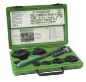
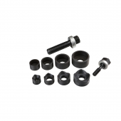
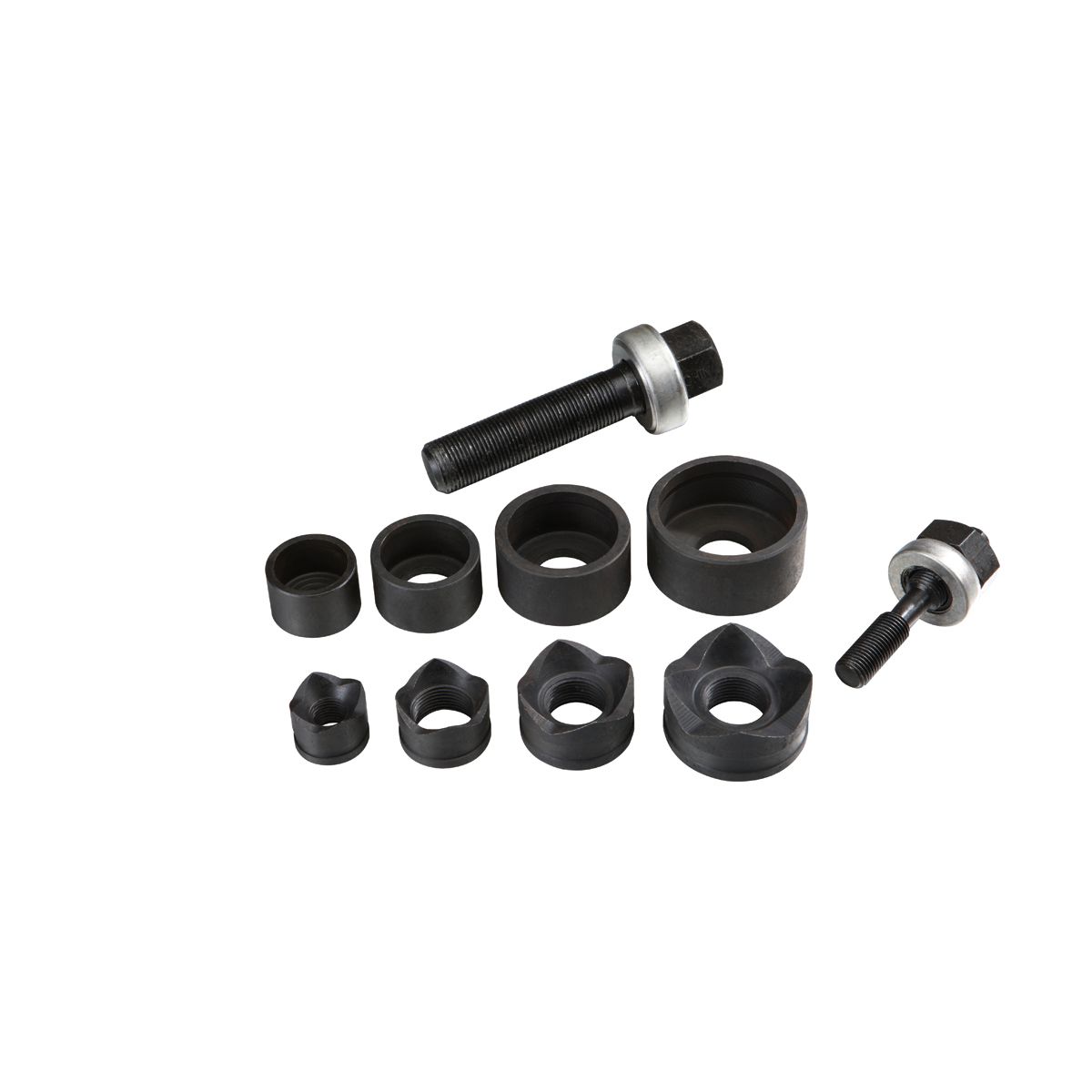
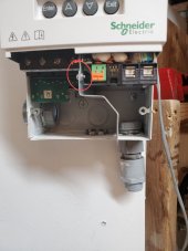
Did you do

1668352864319.png

With a

1668352927207.png

?

I bought a Greenlee

1668352962205.png

for $200 but Harbor Freight has cheaper ones

1668353005051.png

 
Did you do

View attachment 120053

With a

View attachment 120054

?

I bought a Greenlee

View attachment 120055

for $200 but Harbor Freight has cheaper ones

View attachment 120056


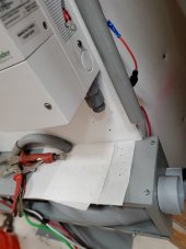
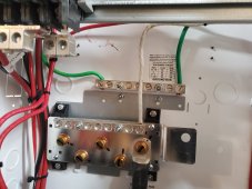
that acutally had a pre-stamped punch out, that would not come out, by the time I realized this, it had deformed. This unit was the first one I bought 4 some years ago and trying to work in that small space was difficult. So yeah, it is ugly.

okay, I might work on that to even it out, while I have it apart
 
I own the harbor freight kit. I can attest that they work well enough for 5-8 holes, but get dull quickly. Even when new they have some frustrations. The dies get jammed in every and any hole.
But for $25 I can complain all day. If I lost this set, I'd still go buy another kit from Harbor Freight.

Also, I don't think you need to run Xanbus/network cable through conduit. Just put a straight relief/protection from the edge of the hole and run the cable free on the wall with some plastic retention staples or zip ties.


I'm a sucker for a clean install. Can you remove the divider and drill through it? It looks like this screw and maybe one more hold the divider in place.
The divider has a bend in the area that lines up with the knockout, so it might require some Dremel work.

Put a short nipple through the divider and the low voltage side to keep them isolated? You've already got a conduit knock out on the right side just attach the conduit to the wall of the charge controller and let the divider end float.

20221112_232049~2.jpg
 
I own the harbor freight kit. I can attest that they work well enough for 5-8 holes, but get dull quickly. Even when new they have some frustrations. The dies get jammed in every and any hole.
But for $25 I can complain all day. If I lost this set, I'd still go buy another kit from Harbor Freight.

Also, I don't think you need to run Xanbus/network cable through conduit. Just put a straight relief/protection from the edge of the hole and run the cable free on the wall with some plastic retention staples or zip ties.


I'm a sucker for a clean install. Can you remove the divider and drill through it? It looks like this screw and maybe one more hold the divider in place.
The divider has a bend in the area that lines up with the knockout, so it might require some Dremel work.

Put a short nipple through the divider and the low voltage side to keep them isolated? You've already got a conduit knock out on the right side just attach the conduit to the wall of the charge controller and let the divider end float.

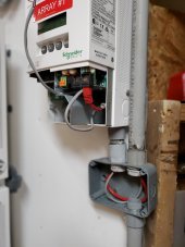
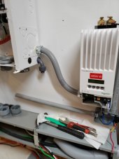
Hey, thanks for the good suggestions. Good ideas, but I am continuing with the 3/4" conduit. I had loose cat 5s on the prior wall and thought about retentions but still wanted conduit to protect them from damage. Also the daisy chaining made for some weird looking wiring.

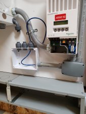
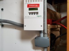
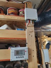
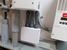
Today I got my first box and got it installed on the #1 CC. The red cat 5 goes up to the Gateway, which is on the opposite wall/shelf and the SCP is downstream from that. Looking forward to powering up the SCP for the first time, as only the inverters provide power for the SCP

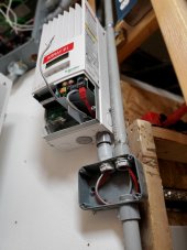
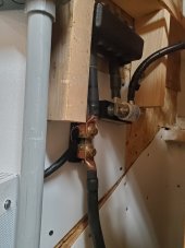
Notice the 2 pair gray cable. Attaches to the AUX contactor and activates a 12v relay near the ceciling which turns on water heater via a DC/AC Optical relay, when the battery is full - the diversion load subsystem

20221113_201251.jpg

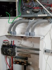
here looking up towards the ceciling. I will probably just paint the conduits white and help them blend in

20221113_201246.jpg


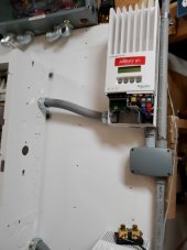
Below CC #2 waiting for the 2nd (and 3rd) box to arrive on tuesay

20221113_201256.jpg
 
Couple more parts came in today

Got the 1" flex conduit measured and cut between the PDP and CC #1 and #2

4 conductors (6awg) plus a ground to each CC - done it before with 90 elbows, now just straights and curvely conduit
the 2 attached to the PDP will be easy


Here is #1, and the upper Xantrex box buttoned up

20221114_213222.jpg


Here is the conduit for CC #2, along with the Lower Xantrex box - still open waiting for 3rd box to come tomorrow, allowing more wiring to be installed.

20221114_213230.jpg
 
Last edited:
last (white) box came in, and installed it


1668573092498.jpeg


And cut and fitted the flex conduit for each of the incoming array lines

20221116_003057.jpg
 
Last edited:
I little background info

I am using this thread as a Show and Tell, but my main reason is, it is a vlog of my build thread where I log pertainent information on what, why, and how I did things. It serves as my long term memory. I also save this pages locally so that I have a backup in case we lose this web site, heaven forbid

I was able to accomplish re-attachment of the Charge Controller #1 which manages array #1, obviously

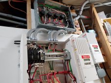
here is the series of pics of the wires coming in from the arrays, through the PDP and into the CC

Entry of the array feedlines enters this box, a re-purposed service panel, on its side
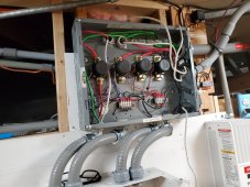
20221117_190908.jpg

Each array has a relay/contactor which can interrupt incoming current. The controller that does is the EVTV V2 Controller - Jack-In-The-Box ->> https://store.evtv.me/products/esp32bms that is between the battery and the bus bars, and thus the inverter

This "jack-in-the-back" or JITB, monitors several attributes of the environment and the battery. If anything falls outside of (settable) parameters, the JITB shuts the entire battery system DOWN hard - it turns it off. One of the things that is shutdown down are the incoming charging streams from the arrays. It does this by operating a signal, which is called CHARGENABLE. Normally OPEN, when things are within parameters, it signals a CLOSE control, which I have wired to a normal 12v relay. When enabledl, it causes these 4 contactors to close, thus allowing charging current to enter into the system. If something is amiss this CHARGENABLE is disabled and the contactors OPEN. During normal operating conditions, these contactors are closed, allowing current to enter.

In the following pic, Array #1 wires enter the PDP on the left with a ground wire, and POS and NEG wires. This is the only ground wired between the contactor box and the PDP. Below that, I also have wired GRID AC IN to the AC breaker on the left
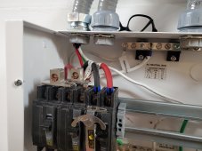
20221117_190919.jpg

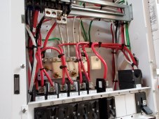
Following the installation instructions, incoming array POS wire enters the 60 amp DC breaker before being run to the CC. The return wire from the CC then enters the top of the next 80 amp DC breaker
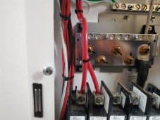
20221117_190923.jpg

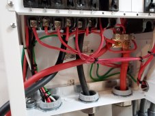
Here a ground, the Array POS (coming from the 60 amp breaker) and the Array NEG enter the conduit to the CC #1. A returning POS and NEG come back the same way
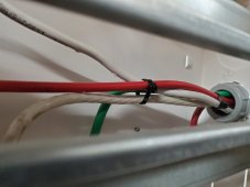
20221117_190928.jpg

here the incoming and outgoing wires from within the CC, a ground is attached at the back wall. This a difficult small space to set these wires, for sure
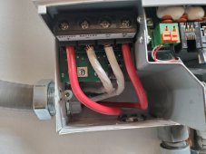
20221117_190934.jpg

this the bottom of the 60/80 amp pair of breakers for CC #1
on the left is the exit wire from the 60 amp, that goes to the CC, and the next one to the right is the exit wire from the 80 amp breaker. This one then goes to the common POS battery bus bar, coming up next
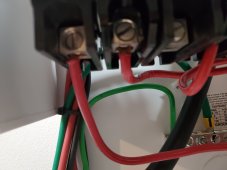
20221117_190944.jpg
 
Last edited:
I saw the PV contactors label in the previous post and was hoping you'd show more on those.

What's the point? The charge controllers can stop PV and the BMS can stop current at the battery, right?
 
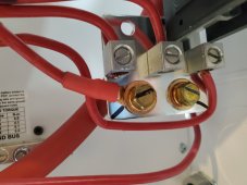
Here is the main POS bus bar within the PDP. I have not yet attached the 4/0 battery lead.

This particular bus bar is the standard one that comes with the PDP. It has space for two 250amp breakers (one installed on the upper right, that open hole can be used for the 2nd 250amp breaker.

This has only 3 lugs for incoming arrays. I have 4, so I used the 4/0 attachment point on the left for one of my arrays. When one buys the upgrade for adding more inverters (to 2 or to 3), a new bus bar is in the package. It has room for 2 4/0 cable attachment and 4 incoming array lugs and 3 mount holes for 3 250 amp breakers.
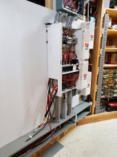
The output from each of the 4 80 amp breakers comes here and is attached
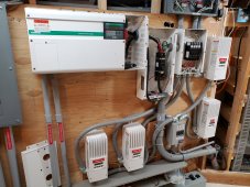


20221117_190947.jpg

here is the NEG bus bar plate

20221117_191036.jpg

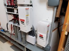
Here is CC #1 finished and buttoned up, ready to go

20221117_191900.jpg

Behind CC #1 is a recessed area for the main POS and NEG bus bars. Here the NEG bus bar has a 400 amp fuse on the incoming lead from the JITB (2/0 cable)

Exiting the bus bar the cable enters the current shunt from my prior configuration. This runs a meter up in the kitchen for quick observation of charging/discharging, etc

20221117_191911.jpg

and finally the Xanbus goes up to the ceciling to the opposing watt (where some of our pantry is) and connects to the retired product Conext Gateway (replaced with the Conext InsightHome). It then connects to the also retired product, Conext SCP. The SCP allow for panel configuration without the need for a computer and browser. I got these before they retired the products


20221117_192148.jpg

An interesting point I found, was that the SCP is ONLY powered by an inverter over the Xanbus. The CC are powered by their battery. Because of this I have not used the SCP at all. It has just been in a box for the past 3 years


Now to wire up the CC 2, 3 and 4

The instructions state to mount the inverter first, then the PDP, but I decided to mount and attach the PDP and ready what I can awaiting for the inverter. BTW, the inverter shipped yesterday - finally
 
Last edited:
I saw the PV contactors label in the previous post and was hoping you'd show more on those.

What's the point? The charge controllers can stop PV and the BMS can stop current at the battery, right?

The JITB has no communications with the charge controllers. When the JITB detects an out of bounds issue, it can disconnect the batteries yes, but the CCs will continue to pump current with no batteries to send it to, not good for the CC

Also Jack Rickard who designed the JITB, had other configurations where this type of control proved of benefit. He had 5 5kw SolarEdge string inverters with 27kw of panels coming into his shop. 15kw inverter, 100 kwh of tesla batteries. He wanted to STOP everthing down, when the JITB detects an issue

Jack was any interesting guy.

He had cash flow. Back in 1997 or so, he installed a PV whole house generator and it cost him $275,000 for the joy of it.

he was into EVs for some time, then switch to solar

his youtube link https://www.youtube.com/@EVTVMotors
 
Last edited:
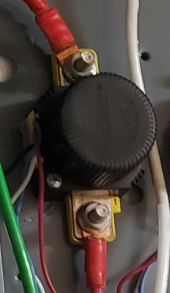
Are those round black cylinders the relays switching PV strings? Do the voltage ratings support it?

1668742901021.png

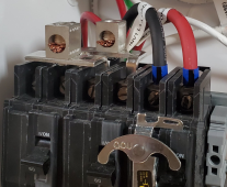
In your interlocked transfer switch breaker panel, interesting lugs/busbars to bridge every other breaker terminal. I assume those have 240VAC between them. I suggest some kind of insulation between and over them.

1668742796511.png
 
Are those round black cylinders the relays switching PV strings? Do the voltage ratings support it?

View attachment 120715

Oh yeah

Gigavac GX1BB 150amp, 12-800vdc, $110 back in 2020

coil is 12vdc


In your interlocked transfer switch breaker panel, interesting lugs/busbars to bridge every other breaker terminal. I assume those have 240VAC between them. I suggest some kind of insulation between and over them


View attachment 120714

I have pondered that same thing, but it is UL Certified

keep the fingers out
 
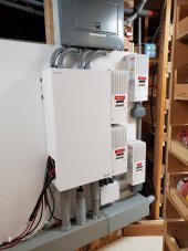
The PDP and the 4 CCs are mounted and wired, save for the actual inverter

starting at the bottom

DavidPoz made a good point of the weight of the 4/0 cable hanging by the bottom bolt of the 250amp breaker, placing strain on it. He came up with a good strain relief solution, which I also followed below

Here are his words on this issue


Below is the pic of that rubber gripper on the NEG 4/0. I installed the same on the POS. And it really provides a good strain relief
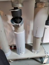
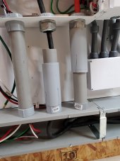
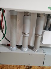
Notice I have installed 7" of 2.5 inch conduit over the main 2.0 inch conduit. It slides up and down and will provide protection to the upper part of the cable when in the up position. I cut 4 slots in the bottom the 2.5 inch to allow for a clamp to be tightened and lock the slider into place

20221118_165535.jpg

another pic

20221118_165824.jpg

looking up at the PDP fully wired and the contactor box

20221118_165829.jpg


upper distribution portion. I have turned on the battery (breaker to injverter off though ) and voltages measure good for battery and charge controllers at various points

you might notice I am missing one of the AC breakers, namely a 60 amp for CC #4
Seems last time I installed the system, I stripped the lower wire mount point, so it no longer works after being removed. Ordered a new one ($54) from Signature Solar and will install when it gets here

20221118_165832.jpg

Lower portion of PDP


20221118_165835.jpg

Pic from the right of what is there

20221118_165844.jpg
 
Last edited:
more pics of the finished PDP

20221118_165848.jpg

Xantrex routing box


20221118_165853.jpg

Left view of the PDP and CCs
with wires hanging out to the left, waiting for the inverter to show up and fling itself at the wall

20221118_165921.jpg


DEFINITELY looks better and utilizes the space far, far better than the zoo I had before. Well, I didn't have the money back then. Now I do. Correction. I did have the money - now Signature Solar has those dollars

Tired, but feel good about the past week's work to get to this point

Solar will charge the battery tomorrow
 
Last edited:
couple of things left to do

1) Install inverter after it gets here
2) Install that 60 amp breaker after it gets here
3) Upgrade L1 and Neutral to 4 AWG between PDP and transfer switch (done)
4) Upgrade Neutral to 4 AWG between transfer switch and service panel (done)

Now 4 AWG between PDP and Service Panel for future 2nd inverter use, don't have to play with it later

BEFORE

Teardown of the Xantrex powerwall.jpg


AFTER with covers back on

20221118_213639.jpg
 
Last edited:
Picked up 2 3" clamps and installed on the conduits, so those are set now

20221119_154933.jpg

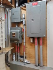
Some work on the AC side of things as well:


Finished upgrading L1, L2 and Neutral from 6 AWG to 4 AWG between the PDP, the transfer switch and the service panel. Planning for future 2nd inverter installation someday

and installed the left front panel of the raceway, so all things buttoned up

20221119_154945.jpg


Did receive 10' of Romex 6/3 for wiring the service panel above to the kitchen's range/oven. Will be adding the 240 v recepticle shortly
 
Fedex delievery of the XW Pro is scheduled for Wednesday 23, Noon to 4PM

You and your son better start eating your wheaties now ?.

Best wishes for an uneventful XW move from the driveway to the powerwall.

That would be a wonderful Thanksgiving if it all goes well.
 
Back
Top