EJansen
Solar Enthusiast
Hi Guys, I haven't been getting much traction in the other posts revolving around my question, so I figured I'd start a new thread here - since maybe it's not a beginner question that belongs in beginners corner. I short, I want to cut my teeth on a smaller project but at some point I want to install Solar for my whole house. I figured I’d start a bit smaller and go with a shed install first to make sure that the requirements are met for passing an inspection, so I sent the attached drawing to my county POCs (in Va) for permitting to ask what I might need to do to pass their inspection. One of the guys responded back, but just said to call him. So I give him a call, and he says that there's several issues with the diagram, but wouldn't tell me what the issues were the only 'example' / hint for one of the issues was in regards to the use of a power cord that plugs the shed into the garage a few feet away (which, I definitely understand that one - if permanent, it should be in conduit and tied in to the house). Regarding his not telling me what the issues were, I'm assuming that it's some sort of conflict of interest? I just thought it was odd, because if I were to pay for the permit and have an on-site inspection, they'd tell me what was wrong / why I failed the inspection, so I don't know why he couldn't say.
This is essentially what I sent to them in an email:
"Attached is a drawing I did for my shed, but wanted to get your thoughts to see what I might be missing. I have some questions based on the diagram that I was hoping you guys could provide me some guidance on:
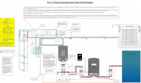
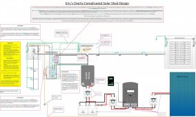
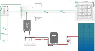
As you can see in the diagram, I don't show grounds on the panels. To maximize roof space on the shed for where the sun first hits, it'll be one 200w 24v panel that's run in parallel with two 100w 12v panels (different roof pitches would allow for different panels). The single panel would be at the cusp of 50v, if going to 125% of PV Imax, but the two 12v panels in series would be just over. Regardless, my plan is to ground the panels, but where in the diagram would you guys recommend tying the ground in? I was thinking that I should just go straight to the grounding bar in the automatic transfer switch, which ties to the house ground using 6ga wire – which, I know is overkill.
Another Monkey wrench to throw in: The house power would come from an extension cord that's plugged into the back of my garage a few feet away from my shed (which has a 15amp flanged inlet on the back of it).
Would the proposed diagram (with the addition of panel grounds / proof the equipment was UL rated) pass your inspection? The questionable part for me, is when the transfer switch {which only transfers hot and neutral} is on solar (the primary source used). Though both solar and home would connect to the same grounding bar in the transfer switch, which would connect to the homes single grounding point, I think all would be well if the transfer switch was connected to ‘shore power’, but most of the time the shed would be on solar.
So if I had a load that had a fault within the shed, and current then travelled over the ground trying to get back to the source, the GFCI would pop, but if for some reason it didn’t, the Inverter should detect it cut off power and go into an alarm state, but I’m pretty sure the breaker would never pop because of the other two safeties before it. Anyhow, just curious if my setup is ok or not and was looking for feedback (even if it's something else that you see missing in the diagram) for passing an inspection?"
With that said, can anyone on poke holes in the drawing / let me know what what issues they see other than the power cord?
Thanks in Advance,
Eric
This is essentially what I sent to them in an email:
"Attached is a drawing I did for my shed, but wanted to get your thoughts to see what I might be missing. I have some questions based on the diagram that I was hoping you guys could provide me some guidance on:
As you can see in the diagram, I don't show grounds on the panels. To maximize roof space on the shed for where the sun first hits, it'll be one 200w 24v panel that's run in parallel with two 100w 12v panels (different roof pitches would allow for different panels). The single panel would be at the cusp of 50v, if going to 125% of PV Imax, but the two 12v panels in series would be just over. Regardless, my plan is to ground the panels, but where in the diagram would you guys recommend tying the ground in? I was thinking that I should just go straight to the grounding bar in the automatic transfer switch, which ties to the house ground using 6ga wire – which, I know is overkill.
Another Monkey wrench to throw in: The house power would come from an extension cord that's plugged into the back of my garage a few feet away from my shed (which has a 15amp flanged inlet on the back of it).
Would the proposed diagram (with the addition of panel grounds / proof the equipment was UL rated) pass your inspection? The questionable part for me, is when the transfer switch {which only transfers hot and neutral} is on solar (the primary source used). Though both solar and home would connect to the same grounding bar in the transfer switch, which would connect to the homes single grounding point, I think all would be well if the transfer switch was connected to ‘shore power’, but most of the time the shed would be on solar.
So if I had a load that had a fault within the shed, and current then travelled over the ground trying to get back to the source, the GFCI would pop, but if for some reason it didn’t, the Inverter should detect it cut off power and go into an alarm state, but I’m pretty sure the breaker would never pop because of the other two safeties before it. Anyhow, just curious if my setup is ok or not and was looking for feedback (even if it's something else that you see missing in the diagram) for passing an inspection?"
With that said, can anyone on poke holes in the drawing / let me know what what issues they see other than the power cord?
Thanks in Advance,
Eric
")