diy solar

diy solar

SolarEdge autotransformer 500 watt idle consumption?

TennesseeGuy

New Member
Joined
Jan 14, 2021
Messages
7
Good day everyone! I'm a beginner getting my first system (off grid) up and running.

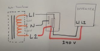
I'm using a growatt 5000es and a solaredge autotranformer for the 120v generation.

I'm currently charging the system now and noticed that there is about a 10-12% load on the system via the growatt display. I don't have anything running at all, I'm just charging via panels and have the tranformer on but no loads on the main panel.

It's showing anywhere from 475sh to 530sh volt amps on the growatt readout, which is about that 10% load.

If I shut the tranformer off, the load on the invetter goes to zero right away.

Should the tranformers idle consumption be this high or is something wrong?
 
No, that is order of magnitude higher than what I would expect.
Are you sure the transformer was not powering some loads?
Is the transformer wired correctly?
 
Definitely no loads on it.

I believe it is wired correctly, Im running L1 and N (L1 and L2) from the ac output of the growatt to my main panel into a double pole breaker. Then another double pole breaker running that L1 and L2 from the main panel to the L1 and L2 of the tranformer. Then N from the tranformer runs back to the N bar on the main panel to create the 120v split.

I did hook a few loads up to see if it worked but they have since been disconnected days ago. I ran my RV off of it to test it as well but it is also not hooked up anymore.
 
It's showing anywhere from 475sh to 530sh volt amps on the growatt readout, which is about that 10% load.
You are seeing reactive power is not real power. Put in into off-grid mode powered from battery and see how many DC amps is it pulling with autotransformer only.
 
I believe it is wired correctly, Im running L1 and N (L1 and L2) from the ac output of the growatt to my main panel into a double pole breaker. Then another double pole breaker running that L1 and L2 from the main panel to the L1 and L2 of the tranformer. Then N from the tranformer runs back to the N bar on the main panel to create the 120v split.
This doesn't sound right... I think it should be wired: inverter->breaker->AT->panel
But it sounds like you have it wired: inverter->breaker->panel->breaker->AT->panel
Your inverter 240 shouldn't go anywhere but the AT (unless you have true 240V loads, which would be uncommon in North America). All loads (120V and 240V split-phase) connect to the output of the AT.

I couldn't find a diagram for the solaredge AT, but here's a link to one from Victron... Just look at the brown block diagram on the right side of the image.
 
You are seeing reactive power is not real power. Put in into off-grid mode powered from battery and see how many DC amps is it pulling with autotransformer only.
I have the inverter set to sbu, but no utility power wired in. It's running off battery only with no AC hooked up from grid or powering any loads. I didn't do an amp test on the wire, I'll do that next and also require it per Lake House's post.
 
This doesn't sound right... I think it should be wired: inverter->breaker->AT->panel
But it sounds like you have it wired: inverter->breaker->panel->breaker->AT->panel
Your inverter 240 shouldn't go anywhere but the AT (unless you have true 240V loads, which would be uncommon in North America). All loads (120V and 240V split-phase) connect to the output of the AT.

I couldn't find a diagram for the solaredge AT, but here's a link to one from Victron... Just look at the brown block diagram on the right side of the image.
So I don't see how my transformer can wire up in that order. There is only one spot to run L1, L2 and N. I can't fit more than one wire into the ports on the transformer. There isn't an input and output spot, just one hookup. I thought that's why everything went to the main panel first.

I'm trying to think of how to wire it together without using the main panel as a connection hub, but if I did wire them in a separate junction box first, the same connection is made as in the main panel, so I don't see how it would make a difference. I will continue to hunt around to see if I can find a way to wire it up the way that you suggested.

Since I had it all apart, I put it back together as I had it and turned it on, and now I'm only getting a .3% load on the system now, about 120-135 va/watts now, nothing like before where I was seeing 10-12% load.

For reference, I was seeing a 40 watt load with just the inverter on, and it went up to about 110-130 watt load with the transformer on.

I'll keep an eye on it as I continue to build the rest of the system out.
Here is a link to the system I am relatively modeled after, if you go to the 9:23 mark you can see the diagram that I followed to wire up the transformer.


Thanks for all the input and help so far everyone, I'll try to keep this thread updated!
 

Attachments

  • transformer diagram.png
    transformer diagram.png
    413 KB · Views: 3
Back
Top