diy solar

diy solar

Source for studs for Eve 280 AH cells?

Where did you get the torque spec? I have EVE 280k cells with the M6 welded studs with the smallish ≈10mm conctact area.

IIRC, it was in the cell datasheet.

I hate the new cells for that reason. It's like a built-in defect. Mine were the ones with the large flat internal threaded terminals. Massive contact area and worked great with grub screws.
 
I hate the new cells for that reason. It's like a built-in defect. Mine were the ones with the large flat internal threaded terminals. Massive contact area and worked great with grub screws.

Agreed. I would have a tough time buying another set of cells at this time because of the funky terminals. The one version that has two connection points would be OK. But that dinky contact area that you refer to really bothers me.
 
Agreed. I would have a tough time buying another set of cells at this time because of the funky terminals. The one version that has two connection points would be OK. But that dinky contact area that you refer to really bothers me.
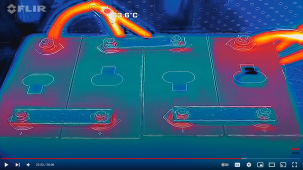
I have seen several videos about the small contact area and surprisingly it doesn't seem to matter. If it is in fact not capable of carrying the required current this fact will manifest itself by the contact area getting hotter than the surrounding surfaces. When tested, the contact area remains cooler than the buss bar or the cells, so it is not a problem. Here is a video of a test with 160A for 20-minuts then 230A for an additional 10-minuts with no heating. The good stuff with a flir camera begins at 22:25. I bought my 280K's with these terminals after watching this test.
 
There's a difference between "this is a good design" and "this is not a problem".

Not sure what you're looking at. I watched the video you linked and saw the opposite.

1669232959613.png

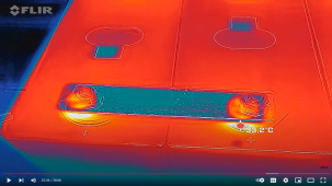
The FLIR imaging confirms it for me... it's a bad design. The fact that there's a temperature rise at all indicates a point of resistance. Those connections very nicely add 8 additional resistors.
 
There's a difference between "this is a good design" and "this is not a problem".

Not sure what you're looking at. I watched the video you linked and saw the opposite.

View attachment 121552

The FLIR imaging confirms it for me... it's a bad design. The fact that there's a temperature rise at all indicates a point of resistance. Those connections very nicely add 8 additional resistors.
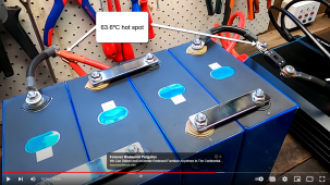
I would say that you grabbed the wrong screenshot. The max temperature on the studs is 33.2ºC and the background temperature of the work bench is 24.7ºC so that is a 8.5ºC rise with 230A for 10-minutes. That is a great result and I do not hesitate to use mine for that purpost. I ahve them connected in a 2p4s configuration with a JK 4S2A20P BMS. Even if I use the max over current limit of 350A that will be 175A per post and only 76% of what Andy tested to. In reality, I will not be going over 200A or 100A per post for more than a few seconds (30s is what I have the overcurrent cutoff set to) so I will be at 43% of this test so I am good with the more robust welded studs rather than the drill/tap terminals that so many have reported stripping.  Those glowing orbs in your screenshot are all in wires and crimps and have nothing to do with the welded studs.small studs.png
 
I have seen several videos about the small contact area and surprisingly it doesn't seem to matter. If it is in fact not capable of carrying the required current this fact will manifest itself by the contact area getting hotter than the surrounding surfaces. When tested, the contact area remains cooler than the buss bar or the cells,

No portion of the video showed this. It showed the opposite.

so I am good with the more robust welded studs rather than the drill/tap terminals that so many have reported stripping.

I take it you've not seen the reports of the welded studs coming off?

The reports of stripping were 100% over-torque and the fault of the user EXCEPT in cases where shoddy cells were supplied. Tapped threads with grub screws and a properly torqued nut yield a notably superior connection. Surface area and pressure are your friend when making terminal connections.

Those glowing orbs in your screenshot are all in wires and crimps and have nothing to do with the welded studs.

Not possible. The sensing wires and crimps carry essentially zero current.

Again, this comes down to a difference between "not a problem" vs. "good design."

The welded studs are an inferior design. Period.
 
No portion of the video showed this. It showed the opposite.


I take it you've not seen the reports of the welded studs coming off?

The reports of stripping were 100% over-torque and the fault of the user EXCEPT in cases where shoddy cells were supplied. Tapped threads with grub screws and a properly torqued nut yield a notably superior connection. Surface area and pressure are your friend when making terminal connections.


Not possible. The sensing wires and crimps carry essentially zero current.

Again, this comes down to a difference between "not a problem" vs. "good design."

The welded studs are an inferior design. Period.
I guess I am not seeing the same things you are seeing. Can you show a screen shot where any of the connection points between the buss bar and the stud are more than 10ºC (about 37ºC) above the room temperature? I cannot.
I had not seen any reports of weld studs coming off, so I did a search for it and came up with two threads. On one, the steel stud sheared off due to over torquing, but the aluminum welded housing was fine. On the other thread, the whole stud assembly came off. You could see that the welding was very substandard with a very light weld which only extending about 1/3 of the way around the base. On my eight cells, the welds are pretty big which makes them a bit ugly but should not twist off. If one of my welded terminals ever comes off, I will probably glue it on with conductive epoxy which has much more than sufficient conductivity than needed given the large contact area between the aluminum stud head and the cell terminal.

I do not understand your comment "Not possible. The sensing wires and crimps carry essentially zero current." In Andy's test there are no sense wires or BMS connected. It is four cells with buss bars which is connected to an inverter and nothing else. (We all know this is not a safe practice for a battery in service but this was done for testing purposes on fully charge cells) My comment was that in the screen shot you posted the bright spot with 63.6ºC temperature was not anywhere near a welded terminal. It was at the tow bolted terminal connections that connected the wires that are coming from the cells and connecting to the invertor input cables.non flir.png
 
I guess I am not seeing the same things you are seeing.

Not sure how.

Can you show a screen shot where any of the connection points between the buss bar and the stud are more than 10ºC (about 37ºC) above the room temperature? I cannot.

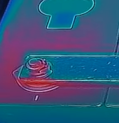
That's exactly what I'm talking about. The terminal to bus bar connections.

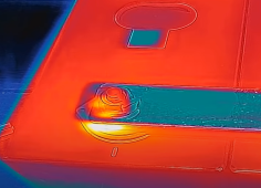
+10°C above ambient and clearly hot compared to the center of the bus bar is not a good thing. You may be okay with it, but it's a poor design.

I'll put it more simply. This is bad. It clearly shows heating at the connection.

1669338347456.png

1669338409532.png

Epoxy? Please link this epoxy. I can find Silver conductive epoxy, but I would hesitate to use something that is roughly 1,000 times less conductive than aluminum and only 1/20th the strength of Aluminum.
  1. Why choose a process with sensitivity to quality that then yields less contact area?
  2. Why NOT chose a tapped hole, a grub screw and proper torque that yields maximum contact area and minimum resistance?

1 is a bad design even if you're okay with the implications.
2 is a good design.
 
I have no problem with using the tapped terminals. I also have no problem with the welded studs. Both perform the needed function in excess of the demand. I purchased the cells with welded studs because that was the only option available on the EVE 280k cells. I could still could have gotten the older cells with tapped terminals, but they were not the 280k chemistry which based on the specs is a more robust build.

As far as the cropped terminal that you posted, it appears to be the left hand of the two terminals in the screen shot that I provided. Given that you have cropped the photo so that it doesn't show the max temperature, I can only guess at what temperature "yellow hot" is in this photo but if it is cropped from my screen shot it is certainly cooler than 33.2ºC (91.7ºF) which is slightly warmer than the ambient temperature in Andy's shop at the time of 24.7ºC (76.4ºF). That is a little bit warmer than the ambient temperature but would make pretty cool bath water which in no way can be construed as "hot".
I assume that you understand how wa Flir camera works. In any view, the hottest object is "white hot", and the max temperature of that white spot is shown on the screen and everything that is cooler than that shades down towards blue. If you take a Flir picture of a glass of ice water, the glass will show as "white hot", the water will be yellow/red, and the ice will be blue. White does not mean hot; it just means hottest in view. If my terminals never get hotter than cool bath water after pulling 230Amps out of 100Ah cells, I will call that a very good design.

No if I look at the first screen shot that you posted, it shows the bolted connection of the wire from the battery to the invertor to be the "white hot" spot at 63.6ºC (146ºF). I would call that hot and in need of improvement to reduce the resistance, while in the same photo, the terminals are blue/red which is very cool and working great.
 
Back
Top