diy solar

diy solar

SRNE 12kW IP65 HES and 10kW ASP

For those who may be interested in inverter settings, they are listed below.
Inverter: SRNE ASP48100U200-H, Software version: 8.17.12, wifi module is connected and setup.

Inverter settings that work for my setup (may be changed at a future date)...... heck, whom am I kidding, something will probably get tweeked within the next few days? hours?...only time will tell:
1 - SBU
2 - 60 Hz
3 - UPS
4 - 51.2 ---> RESETS to 48 MAX, can go lower but not higher then this, manual says max 52, can someone confirm on their unit?
5 - 54
6 - SNU
7 - 180
8 - USER
9 - 56.4
10 - 120
11 - 56.4
12 - 46.8
13 - 30
14 - 48.4
15 - 45.6
16 - dis
17 - 56.4
18 - 120
19 - 120
20 - 30
21 - dis
22 - dis
23 - ena
24 - ena
25 - ena
26 - ena
27 - ena
28 - 70
30 - 1
31 - SIG
32 - SLA
33 - WOW
34 - dis
35 - 48.8
37 - 55.2 -----> manual says max setting of 54... but it accepted my setting without problems... interesting...
38 - 120
40 - 00:00:00
41 - 00:00:00
42 - 00:00:00
43 - 00:00:00
44 - 00:00:00
45 - 00:00:00
46 - dis
47 - 00:00:00
48 - 00:00:00
48 - 00:00:00
50 - 00:00:00
51 - 00:00:00
52 - 00:00:00
53 - dis
54 - current time
55 - current date
57 - 2
63 - ena
68 - 180
end of settings.
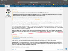
I'll try bumping my 04 up when I head back down to keep working on the ASF's. It might be pendant on another setting to be at xx.xV to get to 52V.
Here's my current ASF settings.
 
Perfect example of voltage drop in my system right now:

My positive wire from batteries to inverter is about 6 feet long (will be shortened later) 1/0 AWG, AC fridge, freezer, PC and one 4 foot light are all running right now. Approx 2200 watt average load. Running on batteries only,
Voltage at batteries 51.97
Voltage at inverter lugs: 51.81

42 amps * (51.97-51.81) = approx. 6.72 watts lost as heat in the bms and wires

Not much of a drop now, but I'd love to see what it will be while it has a 9-10,000 watt load in it???
Next time I'm stress testing it, I'll see if I can remember to take some readings.
 
  • Like
Reactions: D71
I'll try bumping my 04 up when I head back down to keep working on the ASF's. It might be pendant on another setting to be at xx.xV to get to 52V.
Here's my current ASF settings.
Tried changing it to various voltages above the current 49.2 and they wouldn't stick.
I don't remember how I got it to 49.2 when I set things up, I'm almost certain it's dependent on another setting.
 
I'll try bumping my 04 up when I head back down to keep working on the ASF's. It might be pendant on another setting to be at xx.xV to get to 52V.
Here's my current ASF settings.
That's what I was thinking as well, but linked to what other setting?
I've tried it in UTI, SOL and SBU modes, CSO and SNU and it's still the same limit...

I've sent off a request to SRNE Service for clarification since I've already got them looking into a USB communications issue I've noticed.
Could be a firmware issue as well...sigh
 
Wire voltage drop test 2:
Before test:
1700 watt load approx
battery voltage: 51.91
inverter voltage: 51.79

4920 watt load according to the inverter
voltage at battery: 51.13 v
voltage at inverter: 50.73 v
load current: 96 amps
voltage delta: 0.4 volts
96 * 0.4 = 38.4

Thus is lost another glorious 38.4 watts as heat in our endeavour for efficiancy and better large load capability
42 amps * (51.97-51.81) = approx. 6.72 watts lost as heat in the bms and wires
Big difference compared to last test.

My electric dryer just died on me so no full load test for the moment...sigh... one more thing to fix in this never ending story called life.
 
Last edited:
That's what I was thinking as well, but linked to what other setting?
I've tried it in UTI, SOL and SBU modes, CSO and SNU and it's still the same limit...

I've sent off a request to SRNE Service for clarification since I've already got them looking into a USB communications issue I've noticed.
Could be a firmware issue as well...sigh
Really not sure. I'll see if it's any different when I configure the ASPs.
 
When you get your ASPs up and running, please check if they are the same software version as mine... curious to see if they are.
Mine is Software version: 8.17.12
Mine was shipped with 8.17.15 and (displayed a couple of pages later in the LCD display) 1.04. Unfortunately I have no information on what changed in the firmware versions nor what the latest firmware version is.
 
Mine was shipped with 8.17.15 and (displayed a couple of pages later in the LCD display) 1.04. Unfortunately I have no information on what changed in the firmware versions nor what the latest firmware version is.
Should have been listed on page 6 of the lcd display, at the bottom line.
So my software is a bit older already...

Could you please check and see if setting 4 on yours will go above 48 volts? Mine will not even though the manual says 52 is the limit.
 
A lot of good information on battery bank and battery cable sizing. My initial post about the overload shutdown was focused more on why the grid bypass didn't prevent the output power shutdown (regardless of what failures exist on DC side, couldn't the inverter switch to grid bypass output to avoid power interruption?) and why the ASP was stuck in bypass mode afterwards. For the former, it seems that reality is that the inverter will react to certain DC-side faults and shut down AC output, so one just needs to be aware that the grid bypass won't work sometimes. For the latter, Borick indicated that there is a software logic error. In another thread (https://diysolarforum.com/threads/i...old-10kw-48v-split-phase-solar-inverter.71345), a poster indicated today problems with his unit getting stuck and won't change modes after AC input outage, but with a difference that his unit is running in grid export mode. Hopefully SRNE will fix the logic issue(s) in future firmware release.

I do not know the internal wiring size within the LifePower4 batteries. I don't recall seeing this information in reviews.

My current battery bank and cables were sized for the 6000XP; replacing 6000XP with ASP was not part of the plan (the plan was to go with parallel 6000XP and increase the bank size). Currently I'm in unplanned situation of running the battery configuration with an inverter almost twice the intended size (not surprised nor complaining that there could be DC faults when pushed hard). Back when I configured this system, I read through various posts and tables, wanting to using as large of cables as I could. The limiting factor was actually the physical sizes of cables/lugs that could be accommodated. The reseller put together a quote with 1/0 AWG cables and indicated (when I asked about 2/0 AWG) that 2/0 AWG would be challenging in the 6000XP. I'm thankful I went with 2/0 AWG anyway. The applicable lesson might be that nowadays, the inverter has become more of the disposable item, and the batteries the part of the system retained longer. So when setting up battery banks and cables, some headroom would be beneficial and more easily allow the inverter to be swapped with a larger/better unit.
 
Last edited:
Should have been listed on page 6 of the lcd display, at the bottom line.
So my software is a bit older already...

Could you please check and see if setting 4 on yours will go above 48 volts? Mine will not even though the manual says 52 is the limit.
The version 8.17.15 was displayed on page 6 of the LCD. I just wanted to mention that page 8 seems to display a second firmware version number (1.04 on my unit).

My unit already has setting 4 set to 49.2 (whether at factory or by BMS I don't know). Setting 14 is set to 49.6. Once I increase the value of setting 14, then I could increase the value of setting 4. On my unit, using SOC-based thresholds, the equivalent is true (setting 61 must be less than setting 58). The relationship requires that the battery level must first enter into low-capacity alarm prior to switching back to mains power. I do find this requirement annoying (meaning that each night, my unit sends the low-capacity warning and emit beeps all night until the next morning). On the 6000XP, the alarm level and the switch-back-to-mains level could be configured independently (allowing me to reserve the alarm for grid input failure causing the battery to discharge to lower-than-expected level).

In the SunGold thread (https://diysolarforum.com/threads/i...old-10kw-48v-split-phase-solar-inverter.71345), the following relationship was posted (meaning that setting 15 must be less than setting 12, which in turn must be less than setting 4, etc.). This is not documented in the manual.

"【15】<【12】<【04】<【14】<【35】<【37】<【05】<【09】=【11】"
 
Last edited:
Btw srne 10kW rated 20,000w max divide by ~51.2 is around ~390amps. I would think some of that is ac pass??? Think the max dc is ~ 220 amps - on SRNE ASP-10kW so am sure not going to pass muster 20kW but tiny time. Sound ~ Right? I think they sgp did the change in battery wire cable size based on that My Guess. The blue SRNE Asp- 8kW is recommending 3/0 battery cable by sgp and 4/0 for the 10kw. Blue sgp loves big cables. 😁 With pv in the mix and way it is used messes with me. pV power production is crazy…..flux up and down.

Other systems Batteries and cables…Blue. Victron goes big on batteries and cables for surging too …their small 3000 and 5000 have huge cables.. Welding cable with small strands has a lot of parallel current carrying abilities. Victron uses cross section. Inverter Manufacturers are suppose to state breakers-fuse ratings that they recommend. Think UL portion.

With batteries:
Lifepo Battery cell small terminal contacts worry me ….. throw on small bus bar with slot for even more reduced contact area …measure bus bars -reduced…. whew. Wished in 20/20 hindsight had picked double bolt bus bar cells. 😁☑️ I am safe low power consumption and just want capacity run time. My highest energy peak in a year was around 9kW - emergency heat on heat pump. Reserve over head is nice but system all works as designed for personal expectations if a person knows what they are doing. Some Newbies don’t know. Public post must take considerations. Think you guys are doing good job sharing. Stay safe. Watched Will Prowse video and was dying - laughing when he jumped around corner of wall when testing an inverter.

My add I don’t think we should run inverters at max and expect them to last long. Basic logic gas power generators are recommended half loads or lower. Both for fuel ratings and from wave form degrading. We won’t mention UL gas generators vs not. 😁 you guys going parallel with over head are going better route….imho…..

I think you guys doing the parallel setups and leaving head room is safe thing to do. It is nice to know they can be hammer time for a needed max event too. Ppl have to purchase and build system accordingly but how are the new ppl that have never been shocked learn? 😁 The documentation needs to be above board for them. Be nice if it just worked out of the box too. Will Prowse would not have to say great components - crap software in video reviews. Be nice to see his opinion on this one. 😁🤪

Someone recommended a good thermal camera in another thread those are great tools. See the heat realize the point of loss. Phones had software using cameras in phone but did away with it.

Some software guru get to writing take a chance. Quality is an ongoing process with it. If SRNE takes that to next level they will do huge volume take over. Their volume sales might take over now - so many different labels.

How do you upgrade software …. where or who is the support contact with SRNE? 1 of the 5kW relabel versions stated to make sure software matched with version . It did not say how to resolve. My MPP inverter documentation states the same. No real indicated resolve - imagine contact MPP. That process and web link should be easy to find…but that is not the case. Sadly most inverter companies are that way with software. Reading forums EG4 goes in and does remote software access updates to which I don’t like .

IMG_7054.jpeg

Email:

Watching Will Prowse load test EG4 6000xp was pure comedy to me for that scene.
IMG_7055.jpeg
 
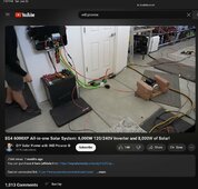
Look again closely - "Recommended battery wiring diameter"
BOTH show 30mm^2 in metric BUT in AWG they show "2AWG" the the very next line "7AWG" ie not the same diameter...although a 7 does look a bit like a 2 ...

2AWG is close to 30mm^2 but 7AWG is only 10mm^2 YIKES!
I pointed that out.
Most new ppl won’t catch that. Most new ppl will put 7awg wire on. 😞‼️ These are marketed towards diy. A tech writer would maybe caught that. Depends on writer. They need to fix it. Same with others. Consistency.

IMG_7057.jpeg
 
The version 8.17.15 was displayed on page 6 of the LCD. I just wanted to mention that page 8 seems to display a second firmware version number (1.04 on my unit).

My unit already has setting 4 set to 49.2 (whether at factory or by BMS I don't know). Setting 14 is set to 49.6. Once I increase the value of setting 14, then I could increase the value of setting 4. On my unit, using SOC-based thresholds, the equivalent is true (setting 61 must be less than setting 58). The relationship requires that the battery level must first enter into low-capacity alarm prior to switching back to mains power. I do find this requirement annoying (meaning that each night, my unit sends the low-capacity warning and emit beeps all night until the next morning). On the 6000XP, the alarm level and the switch-back-to-mains level could be configured independently (allowing me to reserve the alarm for grid input failure causing the battery to discharge to lower-than-expected level).

In the SunGold thread (https://diysolarforum.com/threads/i...old-10kw-48v-split-phase-solar-inverter.71345), the following relationship was posted (meaning that setting 15 must be less than setting 12, which in turn must be less than setting 4, etc.). This is not documented in the manual.

"【15】<【12】<【04】<【14】<【35】<【37】<【05】<【09】=【11】"
Thank you for that info. I confirmed it working on mine as well as soon as I changed setting 14 to be 0.4 volts higher then the value i wanted in setting 4 it allowed the change....sigh.
Like you, I'm amazed that this info is not available in the manual...
 
I pointed that out.
Most new ppl won’t catch that. Most new ppl will put 7awg wire on. 😞‼️ These are marketed towards diy. A tech writer would maybe caught that. Depends on writer. They need to fix it. Same with others. Consistency.

View attachment 223959
Soooo true about newbe's not getting the wire size mis print. Almost happened to a buddy of mine. I told him what size wire to run to his 5k sungolds, then he questioned my sizing and sent me the same misprints this past December. I had to look at it and saw the same error with the #7 size wire but the metric size was correct. This could have been bad if I had not been helping him out.
 
...but grateful it IS available on the DIY Solar Forum! ;)
So far I enjoy being on this site a lot. Lots to learn but also lots to share... best way to learn I find it to sometimes fail. Since failures are what make us question the why, where and when of it all sometimes.
Besides, It's good to have great people to bounce ideas off of once in a while, more brains are better then one after all.
 
I had to look at it and saw the same error with the #7 size wire but the metric size was correct.
so users in EU and AUS/NZ were okay, because they were using metric wire sizes... but the N.Americans were all screwed! :ROFLMAO:
I like to run my own calculations for cable sizes, and in DC I typically go up one size from the result. Short wires don't cost a whole lot more if one size bigger, and I sleep better!
 
Soooo true about newbe's not getting the wire size mis print. Almost happened to a buddy of mine. I told him what size wire to run to his 5k sungolds, then he questioned my sizing and sent me the same misprints this past December. I had to look at it and saw the same error with the #7 size wire but the metric size was correct. This could have been bad if I had not been helping him out.
Oh, and I later found the online user manual had the error fixed, but his physical copy was wrong.
 
If it ain't broke don't try and fit ...
MY ASF is just under 5900KWH of PV harvesting on whatever firmware was loaded from the factory.
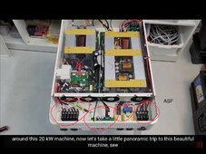
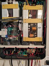
Since you have both the ASF and now 2 each ASP what do you see under the lids? 😁 What is that board on the asp? Did the asf have arc fault?


The ASF was designed for future parallel boards from pictures I’ve seen. The parallel knockout were in ASF case. Future plans.

You have to remember they did change, alter it, fix it, and you bought it. 😁☑️‼️ parallel magic…with upgrades. ‘Ain’t broke” got upgrades.
😁 they were planned

The guts have some changes rest is probably software too. No?

IMG_7061.jpeg

IMG_7062.jpeg

I went snooping what size cables have you been running on your asf? 😁😎 I didn’t know you had that build thread up.

IMG_7065.jpeg
 

diy solar

diy solar
Back
Top