diy solar

diy solar

Stackable Lugs, better than bus bars?

JRP3

New Member
Joined
Dec 10, 2019
Messages
25
Watching David Poz's video about using bus bars to solve parallel resistance issues it seemed like a more complex and less than ideal solution to me.


I thought daisy chaining with cables using a dual cable crimp lug would eliminate extra connections and the bus bar completely, as well as solve his issues with using a solid bus bar directly on the terminals. Did some searching and found "stackable lugs" which seem perfect for the job. https://spectrowireandcable.com/c/battery-lugs/mega-lugs-stackable/
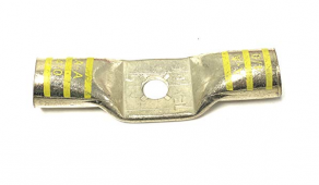
1662395951990.png

Has anyone used these?
 
Watching David Poz's video about using bus bars to solve parallel resistance issues it seemed like a more complex and less than ideal solution to me.


I thought daisy chaining with cables using a dual cable crimp lug would eliminate extra connections and the bus bar completely, as well as solve his issues with using a solid bus bar directly on the terminals. Did some searching and found "stackable lugs" which seem perfect for the job. https://spectrowireandcable.com/c/battery-lugs/mega-lugs-stackable/

View attachment 110351

Has anyone used these?

Stack-able lugs is only an incremental improvement on daisy chaining.
Makes me wonder if you missed the point of the video.
The charge/discharge will not be equitable across the batteries for the same reason that daisy chaining is inequitable.
 
Stack-able lugs is only an incremental improvement on daisy chaining.
Makes me wonder if you missed the point of the video.
The charge/discharge will not be equitable across the batteries for the same reason that daisy chaining is inequitable.
What did I miss? The issue seemed to be related to the extra resistance between the secondary posts on the batteries. He even talked about using a solid bus bar daisy chain to fix that that but didn't like the lack of flexibility. The stackable lugs solves that.
 
What did I miss? The issue seemed to be related to the extra resistance between the secondary posts on the batteries.
The extra joinery of the crimps to the lugs and the extra wires.
Also those lugs potentially make adds, move or changes really not fun.
 
@JRP3 if you have a dc clamp meter, test your method and report your findings.
 
I think those dual-crimp lugs could be used to connect 2x batteries to 1x inverter with perfect balancing of resistance.
Stacked individual crimp lugs would work too.

For 4x batteries, three cables coming off one lug are needed. If 3x stack of individual lugs is too tall for the threads, use of the dual crimp lugs reduces that to 2x stack.

Whether you need perfect distribution of current depends on whether current draw exceeds one battery's capability. If imbalanced, you also cycle one pack more than the other; perhaps with wear it will show greater voltage drop and current draw will start to even out more?

For lead-acid on the other hand, we would want everything perfectly matched.

The only balancing issue I presently deal with is grid AC <--> PV & loads, through paralleled inverter bypass relays. Differences in breaker resistance was a factor, also I think a cross-threaded split-bolt (which I use at breaker terminals; no lugs go there.)

Based on my experience with breakers, a breaker per battery may or may not introduce imbalance, depending on whether they differ. Presumably identical fuses would be a good match. Mixed brands may not.
 
Section 3 of https://www.victronenergy.com/upload/documents/Wiring-Unlimited-EN.pdf covers the topic.

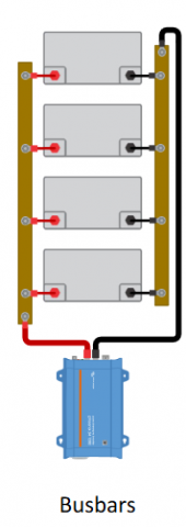
Busbars as used by David in his video is closest to the posts method.
Which gives equitable path resistance and ease of maintenance.
Busbars is even better than posts regarding the latter.
From your link:

The correct way of connecting multiple batteries in parallel is to ensure that the total path of the current in
and out of each battery is equal.
There are 4 way to do this:
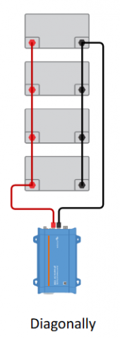
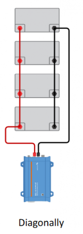
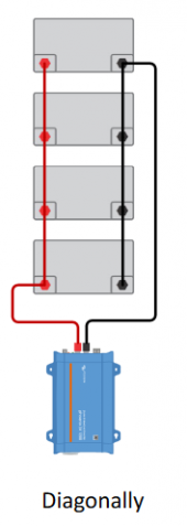
• Connect diagonally.
• Use a positive and negative post. The cable lengths from post to each battery need to be equal.
• Connect halfway. Make sure all cables have the same thickness.
• Use busbars

Daisy chain using stackable lugs and diagonal connection seems to solve the issue.

1662399786458.png
 
I'm not suggesting using the posts method.
I am suggesting using David Poz's method which is closest to "posts".
That is what the thread is about.
You think your method is better is better than modified posts and I think it is only incrementally better than daisy chaining.
 
I am suggesting using David Poz's method which is closest to "posts".
That is what the thread is about.
You think your method is better is better than modified posts and I think it is only incrementally better than daisy chaining.
Can you explain how my method connected diagonally is worse than a bus bar setup and why? I'm not understanding how it would be.
 
Can you explain how my method connected diagonally is worse than a bus bar setup and why? I'm not understanding how it would be.
For the modified posts method each batteries current is on a dedicated bit of wire up to the aggregation point.
For your method the resistance is higher from battery to battery.
 
For the modified posts method each batteries current is on a dedicated bit of wire up to the aggregation point.
For your method all the batteries current is added from battery to battery.
As the current goes up the resistance goes up.
Yes you'd need to use larger cable, just as you'd need to use a large enough bus bar to handle the total current.
 
Anyways, please test your setup and post the results.
I may have to eat some crow.
 
I don't yet have a system I was just wondering why people weren't using this setup other than not knowing about the stackable lug options. I'll certainly try them in the future when I do a parallel system.
 

You can do diagonally from four as shown with only dual-crimp. But it doesn't perfectly balance draw from each battery.

If you do a pair of batteries diagonally, that works. Then make another pair, connect the pairs diagonally in parallel and then to inverter. This is perfectly balanced but requires 3 wires to one terminal.

Either may be acceptable for your applications.

I like to aim for (nominally) perfect, if I think it matters.
(Then I find I have a cross-threaded split bolt, so it became "tight" without pressure on the wire. Which may explain my "balanced" breakers suddenly deciding to trip one in parallel, then the other.)
 
I think I see what you're getting at in a simple diagonal configuration.
1 regular lug to start, then 3 dual lugs on each side with the last dual lug leading to the inverter
..eliminating stacking individual lugs on the battery terminals is a plus (but it's still 2 crimps per post)

One issue issue that comes up is the 'debate' on best practice of fusing each individual battery.
It gets a bit expensive using a recommended Class T for each battery but I lean towards the practice.
I see Will using the diagonal method without consequences so far (as I have for nearly two years), so the debate is open to personal preference
 
Back
Top