diy solar

diy solar

Sun GTIL2 1000 Limiter doesnt work

I glanced at the thread you linked to but he seemed to be using a DC-DC converter between the battery and the Microinverter.

That would solve the issue in the same manner the adapter developed by ncsolarelectric does.

Something needs to limit the input current or there is a problem…

If you are interested in this subject suggest you send ncsolarelectric a PM or give him a call. He is very generous with his knowledge and has a professional background in power electronics…

I would have likely used a dc to dc converter regardless, as the microinverter does not have a customizable low voltage disconnect and reconnect setting like the GTIL does. Without such a setting the microinverter would run your battery down to low voltage disconnect all the time assuming it's voltage range and your batteries voltage range cross over like that.

I also don't think a microinverter will pull every available amp it can get from a battery, if it did, it would try the same thing with a dc to dc converter and the dc to dc converter would shut down from overload as well.

Anything with capacitors in it does have a likelihood of high inrush current when you first connect it though. I would connect a microinverter it to the battery (or a dc to dc converter) using a precharge resistor, just like I do every DC device I connect up to the battery bank.

Maybe you've noticed your GTIL will spark when you connect the battery up to it if it has been off for a while, it doesn't do that if you use the precharge resistor. You can even watch it's DC voltage reading on the screen go up slowly with the resistor attached, and go down when you take it off, before connecting the battery.
I built a precharge resistor into my 3-way battery switch…

The easiest way to stop an inverter from discharging your battery when you discharge to a low voltage disconnect voltage is to use a relay to the 240VAC input…

My SCC has a relay output that is triggered by a user-settable voltage threshold so ‘turning on’ a generator can be the same thing as ‘turning off’ an inverter / load.

I suspect the small adapter developed by ncsolarelectric costs a fraction of what a suitably-sized DC-DC converter will run you…
 
Please do - IIRC, you need to choose either the fixed limit of the sensor limit…
Looks like I was wrong.

You can check both ‘Limit Mode’ / ‘Internal’ and ‘Battery Discharge Power Mode’ and both will be active at the same time. In this operating mode power generation will be limited to the lesser of the Battery Discharge Power Mode limit or the power level determined by the CT sensor to offset consumption (whichever is less).

Also, I wanted to add a bit more color on circumstances that may have contributed to the failure I experenced.

I noticed this warning in the manual:

‘WARNING: Never disconnect the DC wiring connectors under load. Ensure that no DC current is flowing in the wire prior to disconnecting.

I had my first overdischarge event ever the night before the more heavily-loaded GTIL failed. This means that for the first time ever, a runner cell discharged down to 2.5VDC and caused the BMS to cut-off current flow to the inverters.

I was not there when this happened but it is likely that the failed inverter was maxed out and drawing ~40A when the BMS disconnected while the low-use GTIL inverter was probably drawing only ~1.25A.

Powering these GTILs off of a battery protected by a BMS may be a fundamentally risky proposition…
 
@fafrd
Mine won't let me both limit mode / internal and battery discharge power mode at the same time. I can check them. But if I have any watts detected on the ct sensor it just immediately ramps up to full production.. and I have to shut it off to avoid backfeeding.

Of course, mine does the same thing when it's on limit mode, so I suspect I've got something wrong with my unit.

What does your screen look like when it's detecting wattage used on the CT? Is it supposed to be positive or negative?

My unit is running firmware sun-1000g-sun(22-65V)Ver7.1 .
 
@fafrd
Mine won't let me both limit mode / internal and battery discharge power mode at the same time. I can check them. But if I have any watts detected on the ct sensor it just immediately ramps up to full production.. and I have to shut it off to avoid backfeeding.
Sounds like there may be a problem with your CT sensor…

Before I installed my GTIL, I powered it off of a DC power supply and used an extension cord with exposed wires on the other leg so I could play around with all of the settings and understand how it works..

Are you still in your return window?
Of course, mine does the same thing when it's on limit mode, so I suspect I've got something wrong with my unit.

What does your screen look like when it's detecting wattage used on the CT? Is it supposed to be positive or negative?
I get positive Watts of power generation and positive Watts of consumption/import (5-7W).
My unit is running firmware sun-1000g-sun(22-65V)Ver7.1 .
I’d be surprised if FW revision has anything to do with it but if you tell me how, I’ll check mine next time I’m near mine…
 
Sounds like there may be a problem with your CT sensor…

Before I installed my GTIL, I powered it off of a DC power supply and used an extension cord with exposed wires on the other leg so I could play around with all of the settings and understand how it works..

Are you still in your return window?


I get positive Watts of power generation and positive Watts of consumption/import (5-7W).

I’d be surprised if FW revision has anything to do with it but if you tell me how, I’ll check mine next time I’m near mine…

I'm also testing it with an extension cord with an exposed wire. I didn't feel like hooking it up to breaker box for testing either. :p

I'm not in a return window, but since it at least functions when I tell it to run at a certain wattage, I'll survive.

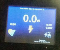
The FW revision (I'm guessing the 7.1 is either the firmware or / hardware revision) is at the very top of the screen when it's in the mode showing you voltage in, watts being produced, etc..

7cc8718228086e5b09b17e4ebd666e74a94976df.png
 
I'm also testing it with an extension cord with an exposed wire. I didn't feel like hooking it up to breaker box for testing either. :p
Powered how?
I'm not in a return window, but since it at least functions when I tell it to run at a certain wattage, I'll survive.
Who did you purchase from? Most vendors offer a 1-year warranty. Are you still within your first year?
The FW revision (I'm guessing the 7.1 is either the firmware or / hardware revision) is at the very top of the screen when it's in the mode showing you voltage in, watts being produced, etc..

7cc8718228086e5b09b17e4ebd666e74a94976df.png
Looks like I’m on 5.1…
 
Powered how?

Who did you purchase from? Most vendors offer a 1-year warranty. Are you still within your first year?

Looks like I’m on 5.1…

Powered by a 24v battery array.

I bought it off Amazon, sold by YongHui on 12/22. If the name YongHui doesn't fill you with confidence, I don't know what will.

7.1 here.
 
Powered by a 24v battery array.
Since the unit displays the consumption / import it is measuring, you should be able to limit output to ~300W (or whatever), turn on a 500W or 750W load, and see what level of consumption gets displayed.

If it is not load - limit (200W or 550W on this example, you know that either your CT sensor is defective or the internal connection has failed.
I bought it off Amazon, sold by YongHui on 12/22. If the name YongHui doesn't fill you with confidence, I don't know what will.

7.1 here.
I purchased from Y&H as well.

Since you are still within your 1-year warranty period, I’d suggest you contact Amazon if you don’t get things sorted out.

Y&H has been selling through Amazon for over two years now and generally, these Chinese resellers are eager to avoid getting blacklisted by customers for dropping the ball on the warranty they claim to offer..

If you have the evidence that the CT sensor input is not correctly being seen by the inverter, my guess is that Y&H at least sends you a new CT sensor to test if not a full unit (possibly after first completing any additional diagnostic tests they may require).
 
@fafrd

I tried while running known loads of varying wattage on the circuit the CT was monitoring. It showed the wattage correctly on the screen, which matched my knowledge of the loads. I also have a killawatt I ran on the load I was running to confirm wattage as well.

It just ignores it, and ramps up to full speed even though it's got the check mark for internal limiter set. Strange thing is, if you have no load on the CT, it drops to 0 output. But even the tiniest load will and it will ramp right on up to full blast.

I suppose to make testing safer, I need to use a higher wattage load so even if it goes up to 1000 watts output it won't export to grid because the load is so high.
 
@fafrd

I tried while running known loads of varying wattage on the circuit the CT was monitoring. It showed the wattage correctly on the screen, which matched my knowledge of the loads. I also have a killawatt I ran on the load I was running to confirm wattage as well.

It just ignores it, and ramps up to full speed even though it's got the check mark for internal limiter set.
So when the GTIL starts ramping up output, does the measured value ob consumption drop down and eventually turn negative (assuming the lays is less than max output)?

Strange thing is, if you have no load on the CT, it drops to 0 output. But even the tiniest load will and it will ramp right on up to full blast.
And you get identical behaviors with the CT sensor positioned both ways?

You are certain that the CT sensor is on the hot leg and not neutral, correct?
I suppose to make testing safer, I need to use a higher wattage load so even if it goes up to 1000 watts output it won't export to grid because the load is so high.
As long as spurious export to grid never last long (>1 minute), you should have nothing to worry about, but yes, the best thing is to test when you have other loads consuming over the maximum ~1kW output (or if you have a NEM agreement, during a low-production day).
 
Well, turns out I'm an idiot and I apologize to the maker of the product (whomever that actually is) for casting doubt on it.

It's not enough that it be on the same leg as the CT sensor and reading the wattage used on the leg correctly. It has to be downstream of the CT sensor as well, thanks @fafrd . If it's not directly downstream of the CT sensor, it does what I described earlier, it reads and displays the wattage being used on the leg, but then just sends it full blast to the leg. If it's downstream of the sensor, it properly adjusts output.

I thought it would only send what it was reading on the wattage from the CT sensor, regardless where it was on the circuit. I figured it used some sort of computer processing of the wattage number to then control how much wattage it spits out. I guess it must instead use some sort of measured resistance on the circuit the CT is on that changes as it sends it's own current down the line.

The product functions exactly as you would think it should when hooked up correctly. You can limit output based directly on sensed load on the leg. You can also limit output independently of any CT sensor, if you want. Say 200 watts regardless of amount detected on leg. You can have no limits, and just output as much as it can, to it's limit.

Or, what I'm doing now, you can cap the output to a preset wattage or amperage maximum, and have it output below or up to that, if it senses less or more than that amount being used on the CT sensor. So you can set it to a maximum of say 200 watts, and if you are only using 50 watts on the leg, it will output 50 watts (ish, it seems to hold a few watts in reserve to avoid exporting). If it detects 250 watts being used, it will output 200 watts.

I can't speak to the longevity of the product, as I've only had it for three months. It does work correctly for now though.
Happy you got it figured out :).
 
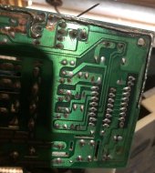
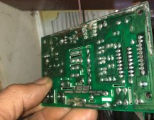
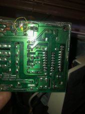
sorry I forgot to mention one thing, the fuse and FET were broken, and in addition to that, the board (copper foil) leading to the FET was also burnt out.
I think there are many people who break the FET with this converter, but I wonder what everyone will do when it broke? go to trash box?
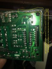
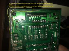
I used to repair (professionally) a lot of motor controllers using parallel Power MOSFET's. Yes the foil burns sometimes and the fix is to use resistor lead wires (or just small gauge wire maybe 18-20ga) to make a "bridge" to the usable part of the foil. I will try to post a picture of something.
Well, looks like one of my two GTIL inverters died today.

I smelled the faintest of smells like something was overheating yesterday but suspected that smell was coming from my BMS.

When this more heavily-loaded GTIL tried to start up this morning, the display switched to a fine-text display with two red lines and then it turned off before I could read what the text said.

I first put that GTIL in service 18 months ago and it has produced ~1800-1900 kWh of power over that time.

I may try to follow your efforts to replace a burned FET but the bottom line is that these GTILs are fragile and cannot take the stress of being run anywhere near their maximum (as you stated).

This unit ran an average of 275W of output (35% of the 800W maximum).
One huge key for MOSFET life is cooling. I am looking at getting a pair of the 2000W GTIL's but warranty or not I believe I will first find a way to improve internal cooling, more or higher CFM fans, even if externally connected and on all of the time. Maybe not applicable for everybody but more cooling will definitely help. Thermal paste is another concern where it connects to the heat sink (hopefully there is a heat sink), you can make sure there is some (unless there are plastic insulators, which case you may not want paste making connection to the heat sink, Im shooting in the dark not actually seeing one of these). BUT if its direct connect to a heat sink you can use some of the computer CPU high thermal transfer pastes that have silver to conduct more/better in lieu of factory pastes as well.

And in another world of possibilities, I used to modify some speed controllers and change ALL mosfets from factory 25 amp/MOSFET to a Siemens MOSFET rated at 60 amps per MOSFET. I don't know what FET's these use, I don't (yet) know if there's an upgrade reasonably available, just some of what I used to do to prevent failures in DC high amp power controls.

Glad to be alive and kicking!
Chuck

I will post those pics of "advance board repair" shortly when I figure out how.
 
IMG_0049MOD.jpg
This repair was on am AC control board maybe 10 years ago, but the principle holds for most any board. I very friendly easy to use item for smaller sections is the lead from a resistor, 1/4 watt usually but can be a 5, 10, 20 watt type if you need more surface area. One detail to note is that you have to scrape the green lacquer board coating off until you see copper or solder will not bond to it. If your not too versed in soldering this is probably not for you either... Just some hopefully helpful stuff since thats what this place is about!

-Chuck
 
Back
Top