diy solar

diy solar

Surge from battery pack?

Derm2044

New Member
Joined
Aug 22, 2023
Messages
8
Location
USA
Hello,

I am struggling to problem solve an issue that I am having with possible surges. I have the following equipment:

12 longi 355w modules 2s1p
1 Sungoldpower tp6048 hybrid 6,000w
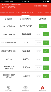
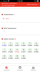
16 lifepo4 cells
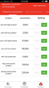
1 Daly BMS with balancer

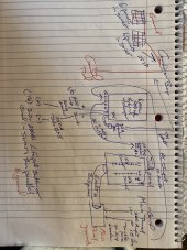
Problem: I am tied into the grid but not feeding back. When the panels are connected to the loads along with utility back up, it’s smooth and no issues. However, I have balance all cells and when they are connected, the panels can charge them, but when I change the setting to solar, battery and then utility, it fires some lightbulbs and electrical equipment. I got a whole house surge protector to install, but feel something isn’t correct.

Any help would be greatly appreciated!
 

Attachments

  • IMG_9140.png
    IMG_9140.png
    432 KB · Views: 5
  • IMG_9141.png
    IMG_9141.png
    445.7 KB · Views: 5
  • IMG_9033.png
    IMG_9033.png
    366.2 KB · Views: 5
Bad inverter? Bad inverter setting? Does it happen when you change the setting, or all the time with the new setting?

Might want to measure voltages when the inverter is not connected to anything.
 
I looked at the neutral and grounding and think it’s ok. I have the panel frames grounded on a separate rod and no ground on the battery, which I’ve seen conflicting information. Below is a drawing and a picture of the sub panel.

Today grid went down and four lightbulbs blew that were on and are on the same circuit if that matters…
 

Attachments

  • IMG_9174.jpeg
    IMG_9174.jpeg
    198.3 KB · Views: 10
  • IMG_9173.jpeg
    IMG_9173.jpeg
    278 KB · Views: 10
As Quattro says, likely open neutral.
We see a white wire for neutral at the breaker panel. How does the wire connect at inverter? How does grid connect?

Can you measure voltage across those blown light bulbs and power strips, with grid connected and disconnected?

Surge protectors (including in power strips) are meant to absorb brief microsecond spikes to 1000V or so. If fed 240V continuous when expecting 120V they may burn.

Different issue, "I have the panel frames grounded on a separate rod"
You should have a wire from PV panel frames back to chassis of inverter. Many of these will cause an AC shock when you touch the frame. Even if ground rod controls that, you don't want electricity flowing through the earth.
 
You have a bunch of loads in the panel but I only see 1 neutral and 1 ground connected... Where are the rest? I always thought every load going to a breaker needed a ground and every 120v load needed a neutral.
Also your wiring feeding the panel appears to be a mighty small gauge...

Can you post pictures of the other panel?

Sound like a wiring issue to me.

I've been running a TP6048 since October with no issues except flickering lights and needing more power.
 
I’ve added pictures of the inverter and main panel also.
 

Attachments

  • IMG_9176.jpeg
    IMG_9176.jpeg
    290.2 KB · Views: 7
  • IMG_9177.jpeg
    IMG_9177.jpeg
    212.6 KB · Views: 7
I’ve added pictures of the inverter and main panel also.
Is it correct to assume all the wire nuts are the loads you extended to the new panel powered by your TP6048?
Where are all off your neutrals in the new panel?

What's going on here?
Screenshot_20230823-185647.jpg
 
Not sure, but I think:

Grid --> main panel
main panel --> inverter
inverter --> sub panel
sub panel --> (hot leads only) of 120V loads

main panel --> neutral leads of 120V loads

If inverter passes through L1, L2 from grid, that's referenced to neutral of main panel. So everything OK.

When inverter disconnects from grid and generates L1 and L2, if it does not bond it's center-tapped neutral to ground, then its output is floating. That puts 240V across your L1 + L2 120V loads, and some get wrong voltage.

If this is the case you need to address neutral switched vs. unswitched, and dynamic bonding of neutral to ground.
 
Holy crap you guys are spot on! That’s why I was struggling to figure it out is because I didn’t really look at the panel side as that’s the one aspect of my project I hired an electrician to do. Not cool!

So now I will need to run ground and neutral wires from the main to the sub bus bars, but how to ground/bond it? Any help or schematics would be greatly appreciated! Thank you!
 
You need to understand how the inverters switches neutral and bonds neutral.
Some inverters have a center-tapped transformer, which can have an issue of trying to rebalance the utility grid. Others, it is two separate 120V inverters.
 
Back
Top