diy solar

diy solar

Synchronous Condensers in an off grid system

hwy17

Anti-Solar Enthusiast
Joined
Nov 11, 2022
Messages
2,770
Location
Santa Cruz, California
I have quite a reverence for the grid as being a kinetic system, and the beauty of the way that spinning generators both impart and absorb energy from the grid innately, not at the speed of a microprocessor's control but in a pure and true analog way.

I have wondered before if there would be any way to apply a small scale synchronous condenser to an off grid system, a rotating mass that would absorb very little power to keep it in rotation and be ready to impart significant power to a short circuit or inductive load.


Anyone have any thoughts on the idea?

The first hurdle is definitely 3 phase vs single phase. I don't have the advanced EE knowledge to know if a single phase synchronous condenser can even be helpful or if the imbalance of the power flow would just make the rotor fight the sine wave in 4 different ways through the revolution clock.

That's where I've got stuck. If they only work on 3 phase then I would first need to build a 3 phase off grid system which is possible but expensive. Then perhaps any quality 3 phase synchronous motor with a rotating mass could help.

If they can help on a single phase system, then there are some details to iron out about what motors will work. My pool pump motor is synchronous single phase, but it supposedly runs at 3450 not 3600 due to some kind of phase angle drift that's slightly beyond my understanding. If allowed to run in freewheel would it come up to a full 3600? Maybe. Can it provide reactive power back through its capacitive supply? I don't know. Perhaps permanent magnet rotors are required or beneficial.
 
It should work for single phase as well as three phase. A 3-phase unit should work with single phase connected (once it gets started); a 3-phase motor will run on single phase. I had a motor-generator Lincoln welder with 3-phase motor and brush-type generator. I got it spinning with 24V of car battery then connected 240VAC.

The motor would spin, with stored energy, and deliver single phase or 3-phase power however it is loaded. Momentum would carry it through the dead times of single phase.

But I'm not sure which type of motor to use. I have 120/240V split phase feeding VFD with rectifier/capacitor front end for 3-phase 2 HP pool pump. It's current waveform, when fed by Sunny Island battery inverter, upsets Sunny Boy PV inverter at the time it tries to qualify the grid before connecting. I spun up a 1.5 HP split-phase pump, hoping it would smooth the waveform, but didn't see any benefit. I thought such induction motors were supposed to draw power when slipping at lower RPM or deliver power when over-driven; maybe they do depend on speed (torque) not voltage.

It may be that a generator, or a brush-type motor, would behave differently. I have a 120V grinder with large brush-type motor. I could imagine getting a generator synchronized, connecting it, then letting it free run. Maybe a motor-generator with separate armatures. I thought some were just 3-phase induction motors with phase shift circuit to get them started.

My pool pump motor is synchronous single phase, but it supposedly runs at 3450 not 3600 due to some kind of phase angle drift that's slightly beyond my understanding.

I think that would be an oxymoron. More likely an induction motor. Perhaps a synchronous motor would do what you want.


I may be mistaking "runs at synchronous speed (3600/1800) or derivative (3450)" with "synchronous motor" and the inductive pool pump doesn't count as synchronous at all then.

About the details of spinning up 3 phase motors and then sustaining on single phase, do you connect the two single phase sources to 2 out of the 3 phase connections or what?
 
Yes, single-phase to 2 out of 3. The Lincoln welder was probably for 208 or 240V, and I put 240V across two windings. Once spinning it keeps spinning. Maybe a capacitor for phase shift to 3rd winding would have started it, or maybe split-phase motors have their starting winding wound differently.

I didn't check if that would make a 3rd phase. I think it is supposed to, with magnetic field produced by windings around stator and other windings shifted. (However, my powering of E-core 3-phase transformers on single phase had some issues.)
 
Kind of related, check out (Different goals, but kind of similar idea...)
Yes the phase converter stuff definitely holds a lot of the secrets. I have thought about whether basically running the entire load side system off the end of a phase converter would achieve the goal.
 
I believe I have heard the AT&T buildings (home office or something? I forget the term) used or still do run off massive spinning converters. But I would guess they were probably doing rotating conversion of AC input to -48v output.
 
Maybe permanent magnet armature and windings on stator would work.

What would happen if you spun up an automotive alternator (with a drill) let it coast, connected two of its windings to AC, gradually ramped up DC to its slip-ring brushes? Thinking it might become a synchronous motor.
 
Other idea I had is maybe a single phase to three phase converter simply being attached on the single phase side, with nothing on the three phase side or maybe an extra mass, would achieve the goal too.
 
Depends on type of motor used for single-phase side. If induction motor, could just get that by itself cheaper.
 
Not sure how the brushless exciter winding works (could be permanent magnet, or AC coupled to rotor but then I'm not sure about how the phases work.)
But the stator would just be center tapped as you say.

Some generators can be paralleled. I haven't worked with that.

The big question for me regarding synchronous condensers is how to deal with RPM change that has to occur for any energy release. Seems like that would involve frequency shift. At least for permanent magnet. Induction motor involving slip, I think just draws or shoves current based on applied voltage. But typically with a phase shift. And depending on voltage?

I think of weights pulling in to maintain RPM. But there is apparently a way to do this without moving parts other than rotation.

 
I'm picturing possibly an AC pool pump motor driving it at 3600 rpm, that being driven by a low frequency inverter. Do you think the pool pump motor and the inverter together would correct the RPM fast enough? I know that the grid is very sensitive to anything under 59hz, but I'm not sure if any devices would mind a couple seconds of 55.
 
There is/was commercial effort to develop residential systems based on this idea but I don't think it's practical in general. It needs a big and heavy flywheel (hundreds of pounds) rotating at high speed to store meaningful energy. It also needs special bearings and air tight enclosure with low air friction to achieve good efficiency. Ongoing maintenance is another issue. There were a few commercial scale flywheel energy products for data centers but they never really caught on. The utility scale systems are viable as they have practical and economic conditions that are very different from commercial and residential settings.
 
The question is what power the motor will deliver.
I tried paralleling an induction pump motor with non-PFC VFD, hoping it would improve voltage waveform. I forget what I saw, but it didn't improve things.

I think induction motor draws power when spinning below 3600 RPM (for 60 Hz), delivers power when spinning faster.
I think you want something which delivers power if input voltage sags.

Brush-type permanent magnet DC motor should do that for DC.
Gotta figure out what does that for AC. Needs frequency set by grid (or inverter), and delivers into that regardless of RPM. Needs a voltage setpoint, which might involve dynamically feeding into a winding to regulate voltage or power delivery.

As for frequency regulations, many things don't care. Inverters monitor by microprocessor, so need to obey their limits (my GT PV has wider limits when switched offgrid.) Brush type and brushless motors vary in speed according to applied voltage. Synchronous and induction motors react when frequency doesn't match RPM.

I have this vision of spinning weights being driven inward to regulate RPM, like an old engine governor operated in reverse.

There is/was commercial effort to develop residential systems based on this idea but I don't think it's practical in general. It needs a big and heavy flywheel (hundreds of pounds) rotating at high speed to store meaningful energy. It also needs special bearings and air tight enclosure with low air friction to achieve good efficiency. Ongoing maintenance is another issue. There were a few commercial scale flywheel energy products for data centers but they never really caught on. The utility scale systems are viable as they have practical and economic conditions that are very different from commercial and residential settings.

I think that is energy storage, supplying an inverter for 60 Hz. Operates over a wider RPM range to extract power, and high frequency due to the RPM. The flywheel ideally is strong not heavy, e.g. carbon fiber. 1/10th the weight but going 10x as fast is 10x the energy.

This thread is about stiffening an AC grid without using transistors to drive the current, something passive that can hopefully deliver massive current for a short time.
 
I think that is energy storage, supplying an inverter for 60 Hz. Operates over a wider RPM range to extract power, and high frequency due to the RPM. The flywheel ideally is strong not heavy, e.g. carbon fiber. 1/10th the weight but going 10x as fast is 10x the energy.
The "ideal" materials and components that should used are a key reason why residential scale systems is unlikely to be practical anytime soon.

This thread is about stiffening an AC grid without using transistors to drive the current, something passive that can hopefully deliver massive current for a short time.
That's what the utility scale systems do. They provide the inertia to help maintain the grid frequency and stability under fault conditions as more inverter based generators (without inherent inertia) connect to the grid. There is also effort to develop inverters with artificial inertia to address this issue.
 
So the question is, what rotating hardware could be repurposed for a residential scale "synchronous condenser".

Do you know what utility scale units contain?
 
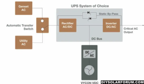
There are flywheel momentum powered units for UPS. Usually used to allow time for a backup generator to get online.

To keep synchronous AC phase switchover requires DC to AC inverter. Bypass directly to generator can be done when inverter slowly slews it voltage/freq/phase to match generator. For jumping back to grid, the inverter is again used to slowly slew the freq/phasing back to grid.

A hybrid inverter with separate grid and generator inputs can perform this resync process between grid and generator, just uses battery instead of flywheel energy.

Pick your poison, flywheel bearing maintenance or battery maintenance.

1693411217380.png
 
So the question is, what rotating hardware could be repurposed for a residential scale "synchronous condenser".

Do you know what utility scale units contain?

The utility scale systems can be pretty exotic. Each vendor has their own secrete sauce. Some use metal alloys (steel, aluminum, magnesium,titanium) for the flywheel but others are using carbon fiber composites. Permanent magnet synchronous machine is commonly used. Various bearing types including superconducting active magnetic bearings. Cooling system (air vs liquid, heat exchanger, etc.) is another area of differentiation.

It's hard to see how a practical and affordable residential scale system could be developed for the average home owners.
 
I wonder if you applied powered backwards into the output of a generator head, would it spin the generator?

It feels like this could inherently be a one ended input/output to rotary device. Power normally flowing to the generator to maintain it's rotation, and then reversing flow when a load pulls down on it. This is reaching the edge of my understanding of the voltage/frequency interaction. Does a load sag the voltage or the frequency on an inverter driven circuit? I'm not sure.

I think the utility ones are "one ended" this way:

1693413471016.png
 
Back
Top