diy solar

diy solar

System Design Feedback Requested

Allistah

New Member
Joined
May 31, 2024
Messages
15
Location
California
Hey all --

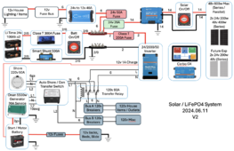
This is my first stab at designing the upgraded system for our 5th wheel. Our daily use is about 850wh/day. I want to make sure I'm not going to burn down our trailer and that I'm not missing anything in regard to wire size or anything else. Thank you for taking the time to assist me in this design - I really appreciate it!

LiFePO4 System v1.png
 
Nice diagram! One thing that stood out to me is that it appears you're going to use your trailer frame as the negative path for your DC system. Typically you would route all your negative wires back to your negative bus bar and not back through the frame of your trailer. Is this your intent or is this just omitted to reduce the wiring complexity in your diagram?

For example: neither your charge controller nor your DC-to-DC converter has a path back to your negative bus bar.
 
Last edited:
I haven’t looked over your diagram in depth tbh. I just want to suggest going with the Multiplus 24/3000 instead of 2000. I had the 2000 and it was great, but 50% higher capacity gives more room for multiple draws that happen at the same time. Even if you don’t think you need it, the price difference will be forgotten next year. If I had gotten the 3000 I probably would have kept it as there are more options for what it could be used for.
 
Nice diagram! One thing that stood out to me is that it appears you're going to use your trailer frame as the negative path for your DC system. Typically you would route all your negative wires back to your negative bus bar and not back through the frame of your trailer. Is this your intent or is this just omitted to reduce the wiring complexity in your diagram?

For example: neither your charge controller nor your DC-to-DC converter has a path back to your negative bus bar.
Thanks for the reply. To be honest, I wasn't sure if that was a problem or not. If all connections to negative should only be done to the negative bus bar, I'll make sure that I do that and do not connect anything to the chassis of the trailer. Could you help me understand why I wouldn't want to use the chassis for ground just so I can understand why?
 
I haven’t looked over your diagram in depth tbh. I just want to suggest going with the Multiplus 24/3000 instead of 2000. I had the 2000 and it was great, but 50% higher capacity gives more room for multiple draws that happen at the same time. Even if you don’t think you need it, the price difference will be forgotten next year. If I had gotten the 3000 I probably would have kept it as there are more options for what it could be used for.
Thanks for the suggestion, I'll take a look at the cost of changing it out to the 3000. The current requirement for the 3000 would cause me to upgrade to 48v batteries I think because the cables would be too large and cost too much. What voltage is your battery bank and using what size cables and fuse?
 
I've made some additional changes to the system based on feedback I got from other sources. The following changes here made:
  • Victron recommends a 200A fuse on wire with 35 mm2 (2 awg) in size for the Inverter above (Changed it to a Class T fuse as well)
  • Inverter provides a special 12v 1A line out to charge a separate start battery
  • Changed the 120v 30A service lines to 10 awg
  • Downgraded the 24v --> 12v converter to 40A (70A wasn't needed)
  • Solar system will be made of four (4) 24v 200w panels in a series/parallel config. To start, it will just be two panels in series (48v) so we don't have start up problems
  • Downgraded the solar wiring to 14 awg based on the current of 4 panels (17A max @ 48v)
  • Colored the two fuses that put DC load on the batteries in pink
  • Colored the one fuse that reduces DC load on the batteries in green
  • Changed the main fuse to 300A and 2/0 wire
  • Changed all 120v 30A lines to 10 awg
  • Updated the diagram with the above changes and attached it to this post
Screenshot 2024-06-11 at 7.31.13 PM.png
 
Personally I would use 12awg instead of 14awg for the pv wires. It’s very little difference in price.


Not trying to change your setup as you know what your needs are. Your diagram shows a decent chunk of money on Victron gear. The price of short runs of wire is small in comparison.
 
Last edited:
Personally I would use 12awg instead of 14awg for the pv wires. It’s very little difference in price.


Not trying to change your setup as you know what your needs are. Your diagram shows a decent chunk of money on Victron gear. The price of short runs of wire is small in comparison.
Yeah, it is indeed expensive - thats for sure. I'll update the 14 to 12 - I don't see an issue with that. :) Thanks for the suggestion!
 
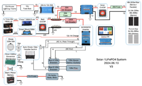
Here is the updated version of my system.
  • Adjusted Inverter fuse and cable size to follow Victron recommendations for this model (200A and 2 awg/33 mm2)
  • Decreased size of DC converter from 70A to a 25A version
  • Changed PV wiring to 12 awg
  • Removed 80A relay to take advantage of inverter AC pass through
LiFePO4 System v3.png
 

diy solar

diy solar
Back
Top