diy solar

diy solar

System Layout Questions Sol Ark 15k and EG4 Batteries

rkwolfe

New Member
Joined
May 5, 2022
Messages
14
I just purchased a Sol Ark 15k, a pallet (33) of Canadian Solar 445W Bifacial Solar Panel | CS3W-445MB-AG, and a 6 pack of the EG4-LL Lithium Batteries Kit | (48v 100Ah) with the enclosure and bus work. This is for an off grid cabin roughly 12 x 20 with a loft. I am also looking at a Sinclair ground mount.

I input the solar panel parameters into the Sol Ark sizing tool and it recommends 30 panels total. The Sol Ark 15k has 3 MMPTs so I was thinking for each MMPT two parallel strings of 5 in series. The math seems to work with 250VOC (Sol ark states 400VOC is max) and roughly 28 Amps max (max with bifacial gain) per each MMPT. The max the Sol Ark can us is 26 Amps but they say it will auto limit Amps on the rare chance the bifacial panels can get that high in Amps.

I am a mechanical engineer with basic electrical training and understanding. I have worked a lot with power plant high voltage and basic home wiring. I know I need some help on the layout and I am looking for any thoughts - good, bad, crazy, etc.

My plan is a Sinclair ground mount with the 30 solar panels. The ground mount is roughly 90 feet from the cabin. I am planning to install a tornado shelter (90% underground) right next to the cabin to use for the battery and inverter storage area. I am hoping it will stay cooler in the summer and above freezing in the winter. Location is southern Oklahoma. From the tornado shelter then the AC output from the Sol Ark would run a few feet to the breaker panel in the cabin.

If the 3 sets of 5s2p is a good idea then I was guessing 8 AWG wire (6 total, 3 pos, 3 neg). The MMPTs on the Sol Ark are limited to roughly that amount of Watts each. Not sure if the voltage drop calculator is factoring both directions but I think that would put the loss at less than 2%?

If the Sol Ark has breakers at the MMPT inputs do I still need or is there an advantage to more protection from a combiner box at the ground mount location? Given the wattage limitations per MMPT at the Sol Ark I am guessing I would need 3 separate outputs and 6 inputs. I know I still need to address grounding from panels to earth ground but I was going to tackle that later.

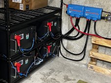
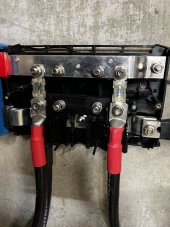
Another question I have and I am guessing others have the same question as I have noticed a couple of folks mention combining the EG4 battery 6 packs (5kW per battery) with Sol Arks - The Sol Ark 15k has two sets of positive and negative terminals to connect the batteries. The max Amp draw from the batteries can exceed the capacity from only one of the pos/neg terminal sets so I will need to split the output from the batteries or run two sets of leads between the battery bus bars and the Sol Ark. Looking at the Amp capacity it looks like you could go with a single set of 4/0 AWG leads from the battery bus bars to a split of some type to the Sol Ark or you could run two sets of 2/0 AWG leads between the Sol Ark and the battery pack. I thought the 2 sets of 2/0 AWG leads might allow for more even draw from batteries if the leads were attached at opposite ends of the bus bars (if that is even possible). I have not picked up the equipment yet so I don't know the bus bar configuration.

This also leads to another question and that is whether I need to have another fuse somewhere in the circuit between the battery pack and the Sol Ark? The Sol Ark wiring diagrams don't show one but if I have to use another set of bus bars to split the battery cables somewhere I thought that might be an opportunity to introduce a fuse to the circuit if needed.

Any feedback would be much appreciated. I know this configuration is simple compared to what most folks are doing but it has been a real technical journey for me. Roof vs ground mount, rapid shutdown (avoided with ground mount), tornado shelter idea for battery and inverter storage, etc. I will share a lot of pictures once I get started.

Thanks
 
If the Sol Ark has breakers at the MMPT inputs do I still need or is there an advantage to more protection from a combiner box at the ground mount location?
No.
This also leads to another question and that is whether I need to have another fuse somewhere in the circuit between the battery pack and the Sol Ark?
Nice to have.
 
MPPT max wire input size is 10AWG.

Max volts 500V @ 26A, range is 125V-425V.

If you wanted to use all 33 panels, you could do 5 panels and 6 panels per MPPT.

Handy tool:

 
Last edited:
I used Victron Lynx Power In x 2 with a Victron smart shunt for my buss bars. Rated 1000 amps. I fused each battery with 300A mega fuses. Ran 4/0 Ancor marine grade wire throughout. Used Ancor 5/16 lugs. Runs nice and cool. You are dealing with an incredible amount of stored and transferred energy. The 4/0 will improve your efficiency. Just my 2 cents.
 

Attachments

  • D2D34B44-2105-4FCF-BF84-C78DEC285D6C.jpeg
    D2D34B44-2105-4FCF-BF84-C78DEC285D6C.jpeg
    1.4 MB · Views: 85
I used Victron Lynx Power In x 2 with a Victron smart shunt for my buss bars. Rated 1000 amps. I fused each battery with 300A mega fuses. Ran 4/0 Ancor marine grade wire throughout. Used Ancor 5/16 lugs. Runs nice and cool. You are dealing with an incredible amount of stored and transferred energy. The 4/0 will improve your efficiency. Just my 2 cents.
Thanks for the photo! Agreed on the amount of energy and I am risk averse. I had not thought about the Victron Distributor. I need something for fuse protection and to split the output from the batteries to go to two separate sets of terminals at the Sol Ark 15k. The Victron looks perfect. The Sol Ark manual states it can handle up to 275 Amps but only 160 Amps total at each set of pos/neg leads (has 2 sets I guess if you want to have 2 separate batteries). Looking at charge rates and running some rough numbers it looks like it could hit upwards of 225 Amps charging batteries if I am calculating correctly so I would need to split that to go across both sets of pos/neg inputs at the Sol Ark. Going to have 6 5kW EG4s in a rack. I am thinking I could run the 4/0 from the battery buses to the Victron Distributor. From there I could split it and run maybe 2/0 or 4/0 (only a couple of feet) from the Victron Distributor to both sets of the Sol Ark terminals for battery input. I like the Victron enclosure the way it houses the fuses. Any recommendations on where to pick up the Distributor and fuses? You mention 300A mega fuses. Are those the ones housed inside the Victron? When sizing fuses I have seen different criteria. I am guessing a 200 Amp fuse at each lead (160 Amp breaker max at Sol Ark breaker) would work? Also - Is that a fuse in the picture with the yellow clips? Is the shunt just for measuring current and would that add any value since I am running it through the Sol Ark? Please forgive my simple questions. I am a mechanical engineer interested in solar but still learning. Thanks
 
Save yourself about $60 per Lynx and buy the power in instead of the distributor.


I ran 2 4/0 positives and negatives from the Sol Ark to my 2 lynxes. I landed the positives one on each end of the buss. The lynxes connect together so you can keep adding them as needed. The negatives I stacked onto a Victron smart shunt then to the lynxes. All cables are equal length. Then I went from the lynxes to the individual batteries also equal lengths to each terminal. 4/0 Ancor marine grade wire. If you watch the above video it will show you how to add mega fuses to the power ins. I have fused each positive terminal from each battery.
 
Update and more questions on the design:

IMG_8929.JPG

IMG_8933.JPG


The Sinclair ground mount kit shows up tomorrow. Planning on the surface ballast method as there are a lot of rocks in the soil here and I don’t want to attempt to drive the posts.

Installed a tornado shelter and set up the EG4 batteries in the cabinet. Has been staying 20 degrees or more cooler than ambient (around 85F). Batteries not terminated yet. All show the same state of charge which I think is good. I was not sure if I had to top balance the batteries before connecting to the Sol Ark but I am guessing it is a non-issue since state of charge is the same on all 6 batteries.

I am thinking of attaching the Sol Ark to the side of the battery cabinet. Would seem to be easier than mounting to the concrete wall. Curious if anyone else has done something similar. I have seen on the EG4 commercials where they mount the inverter inside the cabinet with the batteries.

I am liking the Victron Lynx for the extra fuse protection and to split the positive and negative into two leads for each. The Sol Ark 15k requires two sets of leads if the load exceeds 160A. It looks to me like if all 6 batteries are charging that the load could hit closer to 200A. I think I would also mount it to the EG4 Battery cabinet unless I am missing something there.


I did my best to show the equipment in a diagram. Starting with the 30 solar panels I think I am OK getting those mounted and connected. I will have to get some 10 AWG wires and connectors to get them wired over to a combiner box. I am a little unsure on what type of box to use. The Sol Ark has 3 MPPTs so I need to end up with 3 sets of pos/neg 10 AWG leads. It is supposed to limit Amps to 26 so even though the panels can theoretically produce 28 Amps (likely very rarely) max the lines would likely never exceed 26 Amps. The run is about 100 feet from the ground array to the Sol Ark 15k. My questions are around fusing and grounding. Is it better to go with branch connectors and in line fuses or would it be better to put the fuses in the combiner box. I don’t see any pre-fabricated boxes for 3 sets in/out or 6 sets in / 3 out if I didn’t use branch connectors. The other part that confuses me is the grounding. Looking at NEC code it looks like they recommend an earth ground near the ground mount tying the panel frames to ground (as opposed to running it all the way to the same grounding point as the AC side). That part makes sense to me. I assume I would connect the ground in the combiner box to the same earth ground connection near the panels. Just a little confused about whether the combiner box provides some sort of ground fault detection that trips the breakers? Sol Ark also does not recommend connecting the solar panel array ground to the Sol Ark as a lightning strike might fry the Sol Ark.

From the combiner box the 3 pos / 3 neg 10 AWG wires would run to the Sol Ark.

From the Sol Ark the battery wires have to be split into two positive and two negative leads that get combined to go to the batteries. Someone recommended the Victron Lynx for that purpose and that makes a lot of sense to me. I am curious anyone’s experience connecting the positive and negative leads to the battery pack (6). I have seen on some videos that the batteries will charge / discharge more uniformly if one side (pos) connects at the top of the bus and the other side (neg) connects at the bottom of the bus. I have read that EG4 says it does not make a difference.

Finally I need to size the AC power line / ground from the Sol Ark to the panel box. Just have not gotten that far yet. I am guessing it is about a 12 foot run from the inverter to the panel box. I am guessing I ground the panel box and then I can start installing breakers and wiring the cabin.


Comments and feedback would be welcome. I am enjoying this process, but I know there is a lot that I don’t know.
 

Attachments

  • System lay out 11-4-22.pdf
    222.9 KB · Views: 42
I did my best to show the equipment in a diagram. Starting with the 30 solar panels I think I am OK getting those mounted and connected. I will have to get some 10 AWG wires and connectors to get them wired over to a combiner box. I am a little unsure on what type of box to use. The Sol Ark has 3 MPPTs so I need to end up with 3 sets of pos/neg 10 AWG leads. It is supposed to limit Amps to 26 so even though the panels can theoretically produce 28 Amps (likely very rarely) max the lines would likely never exceed 26 Amps. The run is about 100 feet from the ground array to the Sol Ark 15k. My questions are around fusing and grounding. Is it better to go with branch connectors and in line fuses or would it be better to put the fuses in the combiner box. I don’t see any pre-fabricated boxes for 3 sets in/out or 6 sets in / 3 out if I didn’t use branch connectors. The other part that confuses me is the grounding. Looking at NEC code it looks like they recommend an earth ground near the ground mount tying the panel frames to ground (as opposed to running it all the way to the same grounding point as the AC side). That part makes sense to me. I assume I would connect the ground in the combiner box to the same earth ground connection near the panels. Just a little confused about whether the combiner box provides some sort of ground fault detection that trips the breakers? Sol Ark also does not recommend connecting the solar panel array ground to the Sol Ark as a lightning strike might fry the Sol Ark.
Someone I have been working with suggested running 4 AWG wires from each ground mounts to the next, then eventually 2 earth grounds approximately 10 feet apart from each other.

1669085973754.png
 
From the Sol Ark the battery wires have to be split into two positive and two negative leads that get combined to go to the batteries. Someone recommended the Victron Lynx for that purpose and that makes a lot of sense to me. I am curious anyone’s experience connecting the positive and negative leads to the battery pack (6). I have seen on some videos that the batteries will charge / discharge more uniformly if one side (pos) connects at the top of the bus and the other side (neg) connects at the bottom of the bus. I have read that EG4 says it does not make a difference.

I was planning on having two cabinets of Eg4 batteries, and having the positive/negative from each cabinet connect to the Sol-Ark.
1669086265989.png

But I'm guessing now instead I need a bus bar? Additional fuses just duplicate the 200amp breaker in the Sol-Ark right?
1669086437840.png
 
I think you could use just one of the Victron distributors, but the fuses and it should handle in my scenario both battery chassis. So if you take the cover off I see it working like as follows, pretty cool considering the cost of the bus bars, this seems to work pefect.

1669092318878.png
 
You don't need another set of busbars.
The sol-ark is the aggregation point.
Just fuse the positive wires coming off each rack.
 
You don't need another set of busbars.
The sol-ark is the aggregation point.
Just fuse the positive wires coming off each rack.
It's my understanding you don't need fuses at all, but I though I read somewhere that with 600a of batteries, you could overdraw and trip one of the 200a breakers, so it's best to distribute the batteries between both breakers?

1669093681787.png
 
I just had a look at this video by
by @Will Prowse.
My vision is not good but I think I see each dc positive lug goes to a separate 200 amp double pole breaker.
That means 400 amps aggregate for both positive lugs.
400 fault amps * .8 fuse headroom = 320 service amps.
320 service amps coincides well with Engineer775's claim that the sol-ark can pull 275 amps.
I see no reason to add yet another busbar as the sol-ark's double lugs already serve as the aggregation point.
 
I guess I’m missing something. Why would you have 12 100Ah batteries in two cabinets with all the associated cables, lugs, and cabinets when you could have just six 200 Ah batteries? Seems like a lot of unnecessary points of failure and much more expense. I have 928 AH here (btw those are Victron Power Ins modified with 300A mega fuses for each battery):
 

Attachments

  • 5AD07CB7-4999-49A5-903B-1C2D83CEFABC.jpeg
    5AD07CB7-4999-49A5-903B-1C2D83CEFABC.jpeg
    1,005.6 KB · Views: 33
  • 84F10AE9-9FE8-4E62-B5F1-DAEE85BB5E94.jpeg
    84F10AE9-9FE8-4E62-B5F1-DAEE85BB5E94.jpeg
    920.3 KB · Views: 31
  • 030B5857-9C87-47C9-AA6C-8A7777031A58.jpeg
    030B5857-9C87-47C9-AA6C-8A7777031A58.jpeg
    1.2 MB · Views: 33
I just had a look at this video by
by @Will Prowse.
My vision is not good but I think I see each dc positive lug goes to a separate 200 amp double pole breaker.
That means 400 amps aggregate for both positive lugs.
400 fault amps * .8 fuse headroom = 320 service amps.
320 service amps coincides well with Engineer775's claim that the sol-ark can pull 275 amps.
I see no reason to add yet another busbar as the sol-ark's double lugs already serve as the aggregation point.
To confirm, are you suggesting this configuration is perfectly fine adding a battery bank to each of the two battery inputs on the Sol-Ark? Nothing in between?
1669138286676.png
 
Back
Top