


You are using an out of date browser. It may not display this or other websites correctly.
You should upgrade or use an alternative browser.
You should upgrade or use an alternative browser.
TechDirect BYD BMS in pre-built units: Can anyone read this Chinese label?
- Thread starter GVSolar
- Start date
jasonhc73
Cat herder, and dog toy tosser.
The 12 pin connector is a can bus connection. 2 pins are 24V for the fan, the rest are unknown, completely. Several have tried to figure it out, some have read data, but as for "control" sorry, nobody has cracked that nut.Does anyone know if these units have header for CAN bus communication off them? Victron indicates that they support some BYD units for direct monitoring.

BYD BMS
A no cut, no splice, plug-n-play. It has a screen, Bluetooth, and more settings in the app than we know what to do with. Will already reviewed this BMS. The Inside wires: The Outside Wires: Conclusion: Molex Micro-Fit 3.0 430251000 10POS 3mm Molex Micro-Fit 3.0 or 1729521001...
 diysolarforum.com
More interested in knowing if the Victron will "see" the battery and monitor it within ColorControlGX. Similar to the way they can for Battleborn and even the ByD B-Box BMS units. Guess I should just pony up and buy one and test it.
 www.victronenergy.com
Victron & BYD [Victron Energy]
www.victronenergy.com
FlyinBrian
New Member
- Joined
- Feb 15, 2020
- Messages
- 85
Does anyone know why the BMS wouldn't reconnect? I have a friend with 5 of these wheeled units and the voltages dropped down low enough the disconnect via the BMS. Only one turned back on when 24v was applied to the load side. How do I get the rest to reconnect?
FlyinBrian
New Member
- Joined
- Feb 15, 2020
- Messages
- 85
very interesting.So I bought one of the TechDirect BYD BMS units. I see it show up on Bluetooth. Anyone have a link to the App/Software for it?
(I emailed TechDirect but no response and none of my searches turn up anything.)
GVSolar
Solar Enthusiast
- Joined
- Jan 6, 2020
- Messages
- 455
So I bought one of the TechDirect BYD BMS units. I see it show up on Bluetooth. Anyone have a link to the App/Software for it?
(I emailed TechDirect but no response and none of my searches turn up anything.)
When I read about you getting a bluetooth signal I tested my units - no discernible pairing signal on my phone or iPad. Of course the BMS is buried in a metal case on my pre-assembled units... details about your matching protocol? ID? Pairing device?
GVSolar
Solar Enthusiast
- Joined
- Jan 6, 2020
- Messages
- 455
Does anyone know why the BMS wouldn't reconnect? I have a friend with 5 of these wheeled units and the voltages dropped down low enough the disconnect via the BMS. Only one turned back on when 24v was applied to the load side. How do I get the rest to reconnect?
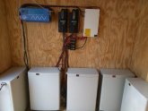
I have 4 of those units in parallel. Working flawlessly. Might I suggest applying a charge to them one at a time? You can use the circuit breakers to disconnect/reconnect them - assuming they are wired correctly. Also, not clear about what you mean by the "load" side...
Attachments
When I read about you getting a bluetooth signal I tested my units - no discernible pairing signal on my phone or iPad. Of course the BMS is buried in a metal case on my pre-assembled units... details about your matching protocol? ID? Pairing device?
I connected the BMS while watching my phone in discovery mode. Saw a mac address pop up, but it wouldn't let me connect or pair.
Official response from TechDirect:

So anyone know of another decent 8S LFP BMS that will handle low temp cutoff, handle 150A & preferrably have a screen? I know there's the Chargery and I've built one pack from 180AH prismatic cells for another project. Was hoping for something like the DALY or ANT versions, but with low temp cutoff.
So anyone know of another decent 8S LFP BMS that will handle low temp cutoff, handle 150A & preferrably have a screen? I know there's the Chargery and I've built one pack from 180AH prismatic cells for another project. Was hoping for something like the DALY or ANT versions, but with low temp cutoff.
Roger Barr
New Member
- Joined
- Sep 3, 2020
- Messages
- 2
I am charging one of these now and my charger is set to charge to 29.2 volts. I am currently seeing 29.21 and still charging at 8.52 amps constant voltage. The current continues to go down. I will update when current drops to zero. I bought my BYD 24 volt 220 Ah batteries and the BMS you are referring to here as stand alone items and wired them myself. I have 8 of each and because of health issues I can no longer seek my goals of solar independence from grid. All the batteries and BMS’s are for sale. BTW I am still charging at 7.5 amps.Official response from TechDirect:
View attachment 12612
So anyone know of another decent 8S LFP BMS that will handle low temp cutoff, handle 150A & preferrably have a screen? I know there's the Chargery and I've built one pack from 180AH prismatic cells for another project. Was hoping for something like the DALY or ANT versions, but with low temp cutoff.
Roger Barr
New Member
- Joined
- Sep 3, 2020
- Messages
- 2
In addition, I am capacity testing @ 0.05C because I have only a 3 ohm resistor @ 1000 watts for that use.I am charging one of these now and my charger is set to charge to 29.2 volts. I am currently seeing 29.21 and still charging at 8.52 amps constant voltage. The current continues to go down. I will update when current drops to zero. I bought my BYD 24 volt 220 Ah batteries and the BMS you are referring to here as stand alone items and wired them myself. I have 8 of each and because of health issues I can no longer seek my goals of solar independence from grid. All the batteries and BMS’s are for sale. BTW I am still charging at 7.5 amps.
augiedoggy
New Member
- Joined
- Oct 26, 2022
- Messages
- 142
Big Battery recently broke up with their manufacturer (Battery EVO) The specs big battery were using seem to be inflated from the actual manufacturers specs on the same batteries they also sell under thier own brand... They even recommend and sell the wrong voltage charger (58.8v) to go with the 16s lifepo4 packs they sell..TechDirectClub.com sells them for $150 - spec at their website. They come installed in the pre-built units that are now sold at BigBattery.com. As far as I can tell, there is no way to interface, program or read information from the BMS - hence my question about the translation.
EDIT* sorry just realized this is a necrothread..
Similar threads
- Replies
- 11
- Views
- 740
- Replies
- 9
- Views
- 262
- Replies
- 2
- Views
- 193
- Replies
- 15
- Views
- 1K