I have a 5 degree slope and also wanted to have the array match the slope for a 52' wide array.
After searching many places for something better I finally used Iron Ridge hardware.
To get a permit my array needed to be engineered. The engineer that Iron Ridge customer service referred me to, said to use shims at the top caps to deal with the 5 degree slope. But for one the u-bolts were too short for that. Also the Iron Ridge customer service guy said the top caps should be at 90 degrees!
Then after already being paid, the darn engineer stopped responding to me when I asked for options other than the shims.
So I was left with expensive engineering for an unbuildable design. What to do next kept me up at night.
So I submitted the engineer's plans, but then opted to not use the shims. Rather I opted to put a slight 5 degree bend at the top of each vertical so that the top caps could mount at 90 degrees as specified by Iron Ridge. This worked great and fortunately the inspector didn't complain.
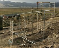
While the cement cured and before the rails and panels were mounted it looked like this:
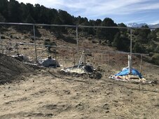
The bend is almost not noticeable unless you look. It allows the verticals to be true plum for optimal weight support. And it allows the downhill side of the array not to be so high in the air, meaning the ballasted foundation blocks didn't need to be as many or as huge as if it was more like a tall masted sailing ship.
(Note, under the tarps are insulated ballasted foundations to protect from freezing as they cured, i.e. huge concrete blocks embedded about 24" deep. A ballasted foundation was used because the ground is hard to dig or bore into here.)
But I had a lot of trouble figuring out how to bend the heavy 3" I.D. mechanical tubing. After calling all over, I couldn't find anyone who could bend these pipes.
In the end, the local welder lent me the old die from an old broken tubing bender he had (orange die in photo below), and I used it with my 27 ton log splitter in vertical mode with a bunch of fancy supports below the tubing including my dad's old anvil to cleanly make the bends without crushing in the front-side or backside from the high force needed for the bends. I got it to bend a test pipe first, then once this worked, launched into bending the actual vertical tubing.
I don't recommend this as it was very labor intensive, but it was the only solution I could come up with.
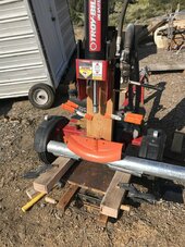
Note! While bending the free end of the pipe being bent needs to travel upwards! So this pulley and weight system counterbalanced as it was being bent so as not to crush the one underside of near the die.
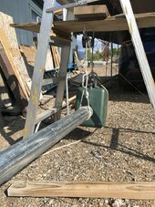
I drilled all of the brace holes on my garage floor (3/4" bolt holes), then assembled them again after hung. This allowed me to get accurate brace holes with much less trouble.
Also hanging this much weight was tricky and dangerous. You can see the chain hoists to lift the heavy side. The tall leg ended up being set on a dobie (small concrete block used to support rebar) adjusted to make sure the long horizontals were straight.
The short leg was supported with temporary vertical 2x4s during the concrete pour and located N-S with wooden spacers between tall and short legs as seen in the first photo above to hold precise dimensions.
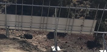
Note, my panel tilt angle is 45 degrees which makes it easy to keep the snow off. Also the short leg is high enough for a fair amount of snow to dump without covering the bottom panels. (Last winter we had a 50 year dump of snow, so I'm glad I allowed this much space for snow, as I expect we might get another 50 year dump once el-nino comes back around.)
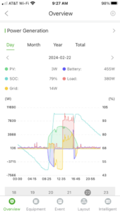
And the result is something like this energy graph on a sunny day.
