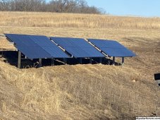
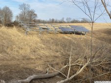
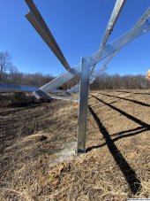
Looking for any ideas on the best method to hold piers in place when using IronRidge ground mount hardware. Site has about a 10 degree slope in the East West direction and I am looking to follow the contour of the hill. Since IronRidge uses 90 degree top caps, my piers will not be able to be vertical but will be perpendicular to the slope of the hill. Wondered if anyone has some experience on how to best hold everything in place before pouring the concrete into the footings. Thanks.
You are using an out of date browser. It may not display this or other websites correctly.
You should upgrade or use an alternative browser.
You should upgrade or use an alternative browser.
Techniques for installing piers with IronRidge ground mount on sloped ground.
- Thread starter tomski72
- Start date
Your piers are are not level or the pipes, or both?Looking for any ideas on the best method to hold piers in place when using IronRidge ground mount hardware. Site has about a 10 degree slope in the East West direction and I am looking to follow the contour of the hill. Since IronRidge uses 90 degree top caps, my piers will not be able to be vertical but will be perpendicular to the slope of the hill. Wondered if anyone has some experience on how to best hold everything in place before pouring the concrete into the footings. Thanks.
Yes. Array is 37' long and last pier would be about 7-8' tall on the downhill side (west side). And that's just the south pipe. With a 30 degree tilt, the north pier would be even higher on the downhill (west) side.Why can't the piers be vertical? Too much of an elevation difference between the furthest piers?
That’s going to be difficult. You won’t be Abel to use a level. You will need lots of string and a laser to line everything up.Piers will not be vertical and pipes will not be level as the pipes will follow the 10 degree east west slope of the hill.
OffGridForGood
Catch, make or grow everything you can.
you can assemble the vertical and horizontal pipes together with the Tee-clamps and support them on either wood X's or scaffold frames (if you have these) between the uprights at the slope you want. Auger the holes for the posts, check the alignment brace and pour.
This is unwise.
None of your panels will be getting equal solar angles...
You should make sections plumb and level, if you must follow thw contour, make series sets and stairstep to the slope...
Everything in series needs to have thw same angle facing the sun...
None of your panels will be getting equal solar angles...
You should make sections plumb and level, if you must follow thw contour, make series sets and stairstep to the slope...
Everything in series needs to have thw same angle facing the sun...
Maybe I'm misunderstanding his plan but if I'm not then the all panels will be at the same angle but the whole array will be tilted 10 degrees EW.This is unwise.
None of your panels will be getting equal solar angles...
You should make sections plumb and level, if you must follow thw contour, make series sets and stairstep to the slope...
Everything in series needs to have thw same angle facing the sun...
timselectric
If I can do it, you can do it.
- Joined
- Feb 5, 2022
- Messages
- 18,637
The top of the rails can be ran with the slope.
But the supports should be plumb for strength.
It can be rough to accomplish, depending on what material is used for the racking.
I'm going to build a south facing ground mount on a east/west 30° slope.
My plan is to keep the top of the array level. And step the bottom panels with the slope.
Basically a triangle shaped array.
SilverbackMP
Solar Addict
- Joined
- Apr 4, 2022
- Messages
- 928
SilverbackMP
Solar Addict
- Joined
- Apr 4, 2022
- Messages
- 928
On a reread, I think the circumstances are different that my application. OPs is facing south but on a east west slope. Wants to follow contours. Yeah, I would use multiple independent mounts and stair step them and use various lengths of pipes encapsulated with some amount of exposed concrete pillars (sonotubes) above grade (and below) to keep things level.
Would likely still use Sinclairs for simplicity but it could be done with Iron Ridge. I would want competent help.
Would likely still use Sinclairs for simplicity but it could be done with Iron Ridge. I would want competent help.
OffGridForGood
Catch, make or grow everything you can.
You could do that.Site has about a 10 degree slope in the East West direction and I am looking to follow the contour of the hill.
Or you could modify the top of the post/plate angle to change it from 90-degrees to 80-degrees (or whatever angle you need for the cross slope).Since IronRidge uses 90 degree top caps,
The piers tilted 10-degrees will introduce a lateral load, at 10-degrees this will be 17.4% of the vertical loads. ie significant. lateral bracing would be advisable.my piers will not be able to be vertical but will be perpendicular to the slope of the hill.
temporary scaffold or wood structure to hold the top rail at the correct height, slope, and alignment. brace the vertical posts from moving during the concrete pour.Wondered if anyone has some experience on how to best hold everything in place before pouring the concrete into the footings. Thanks.
OffGridForGood
Catch, make or grow everything you can.
If you can't modify the angleOr you could modify the top of the post/plate angle to change it from 90-degrees to 80-degrees (or whatever angle you need for the cross slope).
Perhaps shim the top caps:
From the top cap diagram - attached
the cap is 7.5" wide.
at a pitch of 10-degrees your pipe would need 1.3" of shimming stock on one end of each cap. (are the U-bolts long enough?)
If you're handy with metal working, and can weld a pipe seat near the U-bolt location this could be another solution to the cross slope.
Attachments
Hedges
I See Electromagnetic Fields!
- Joined
- Mar 28, 2020
- Messages
- 20,695
You won’t be Abel to use a level.
Could make a 10 degree wedge shaped block, put two levels on it.
you can assemble the vertical and horizontal pipes together with the Tee-clamps
Yes, need pipes lined up. Preferably tops lined up too so they don't need to be cut.
The "horizontal will be several pieces with multiple supports each, so assemble as you go with supports on end of each (aligned by 2x4 and/or straps), then go back and hang any intermediate supports.
if you must follow thw contour, make series sets and stairstep to the slope...
Staircase needs spacing to avoid shadows. Slope in X and Y doesn't.
Similar idea for panel on wall of building under eaves. If pushed out to it starts at edge of eave rather than under eave, avoids shadow moving across it (but more structure required.
Maybe I'm misunderstanding his plan but if I'm not then the all panels will be at the same angle but the whole array will be tilted 10 degrees EW.
Seems like a good plan.
Top bracket with tilt could have been another.
Gravity will want to push the uprights over, but not much at 10 degrees. Diagonals would of course make it rigid.
Any other sideways forces, like wind or earthquake?
The top of the rails can be ran with the slope.
But the supports should be plumb for strength.
Except for his 90 degree "T" brackets.
Ugly trusses would completely take care of strength. Thin cables carrying tension work too, have seen in some pictures here.
OffGridForGood
Catch, make or grow everything you can.
On a closer look the caps are Mag-Alum alloy - not going to be a good idea to modify or shim.
missed that first time through.
missed that first time through.
Hedges
I See Electromagnetic Fields!
- Joined
- Mar 28, 2020
- Messages
- 20,695
OffGridForGood
Catch, make or grow everything you can.
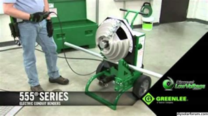
Yeah because EVERYONE is set up to bend 3" Sch 40 steel pipe! LOL!For up to 2" uprights, just curve the top 10 degrees
View attachment 173564
(I've got one of these in my garage; doesn't everybody?)
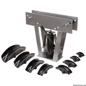
Cheaper non-electric variety:
View attachment 173565
Or if the OP can weld, they can cut a 5-degree angle like you say a foot or less from the top, turn the short piece 180-degrees and weld it back together again. Starting to sound like a lot of work for a bit of slope.
If they can tolerate it, cables or cross bracing members between the tilted uprights will be less effort, but more material.
OffGridForGood
Catch, make or grow everything you can.
OP is NE of Sacramento (Auburn, CA) I believe.Any other sideways forces, like wind or earthquake?
seismic will be a requirement.
Similar threads
- Replies
- 24
- Views
- 1K
- Replies
- 2
- Views
- 462


