diy solar

diy solar

Three phase grid connected inverter

ff003

New Member
Joined
Mar 14, 2024
Messages
2
Location
Australia
Hi everyone,

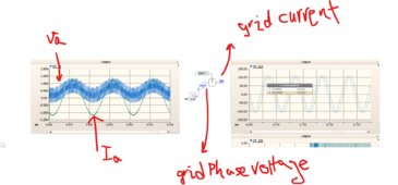
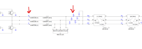
I am working on the system which is shown in the attached photo. For controlling the system I consider the line current and the phase voltage that I shown in the other photo. As I used two transformer I expected the voltage and current be in the same phase in the grid side also, but they are not. Can anyone please help me regard to which parameters of the system I should consider for the control to have in phase voltage and current both in the inverter side and grid side?? Thanks.control.pngmodel.png
 
What results are you getting?

No-load, current into transformer would lag due to inductance. I haven't checked, but am thinking this would cause phase shift of induced voltage on secondary. With some load, it is complex R-L, shifting phase.

Are your transformers being operated in their intended step-down or step-up direction, or are you driving any reverse? In particular, driving WYE to generate Delta is usually reverse. Transformers are far from ideal, and primary & secondary are wound differently (more leakage inductance for primary) which reduces inrush. I also have found current draw to be excessive even after first cycles.

Are you trying to form the grid, or is grid formed on 132 kV side and you're trying to make a GT PV inverter?

You've put this under "Beginner's Corner", maybe belongs under "Inverters" or "Danger Zone!"
Some other guys here have designed and built inverters including "Warpverter"
 
Thanks for your reply.
p2.pngsystem.pngI attached the photo of the results.
I am using step up transformers, 0.4/11kV and 11kV/132kV.
The system is grid following system and grid is connected to the 132kV part. I attached the photo of the system.

I am beginner in this area and maybe my questions are so simple, because of this I posted in this forum.
 
I am using step up transformers, 0.4/11kV and 11kV/132kV. . . I am beginner in this area
This is somewhat terrifying.

I would recommend you find someone in your area who is an electrician and go to him with your questions. The Internet is great when you have general questions - not when you are working with a 132,000 volt system and aren't sure what's going on.
 
Is your problem that current isn't in-phase with voltage at the grid?
Maybe that is lag in the drive circuitry, or phase shift in the transformers (something I'm not sure of.)

I think you can sync a PLL or digital sine wave source to the grid, and make it lead or lag to adjust phase. Phase shift can be desired to help with loads on the grid, or to deliver more power without driving voltage too high. Look for "Volt-Var" and "Q on Demand"

This is somewhat terrifying.

I would recommend you find someone in your area who is an electrician and go to him with your questions. The Internet is great when you have general questions - not when you are working with a 132,000 volt system and aren't sure what's going on.

My first thoughts. But I think he is designing in a circuit simulator, with a notional grid design.

Likely no electrician near him deals with 132kV. 600V, sure, 11kV, maybe. We see videos of working on high tension lines by helicopter.
 
I wonder how detailed your transformer models are. Ideal? Or do they include saturation and hysteresis? I did some work measuring BH curves, then making Chan models in Spice.
 
I'm not an expert on this, but here is my two cents.

In a delta based system the power is the difference between two hot legs. In the Y configuration the power is the difference between a single leg and the neutral. The phase difference between the two hot legs is 120 degrees. So if you change your refence point from the lagging phase to the center tap, you are lose half of that phase angle. So I would expect there to be a 60 degree shift in phase when going from one system to the other.

You also show capacitors in the circuit which will cause a phase difference between voltage and current.
 
Last edited:
Back
Top