ABYC which is the marine standard allows 4 such conductors on a single post. It is true that the higher in the stackup you go, the more resistance there will be. I typically never use more than 2 heavy hitters on a post. The only time there may be a third would be a voltage sense line which is a tiny amount of current.Thinking on this, it makes sense to me that putting all conductors in a single lug would be less oxidized connection points, therefore less resistance in the circuit.
I KNOW, code does not allow multiple conductors under a screw terminal not specifically designed for it, but a lug sized for the total # of strands and properly crimped would be a better solution than crimping two or three etc lugs, and placing them under a single terminal.
You are using an out of date browser. It may not display this or other websites correctly.
You should upgrade or use an alternative browser.
You should upgrade or use an alternative browser.
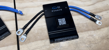
Two cables crimped in one lug?
- Thread starter Swgraham2
- Start date
Pappion
Retired Engineer Tech
- Joined
- Nov 26, 2020
- Messages
- 552
BMS is different. Wires are soldered to Printed Circuit Board. So they use multiple wires and solder points. Distributes the current better across the copper plane to multiple FET switches. I also think the wire contact area increases and decreases the solder bridge area.I did something similar to my BMS', there is 2 P- & 2B- which had to be extended for the boxes to set them where they were needed.
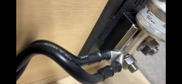
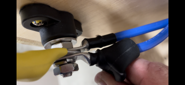
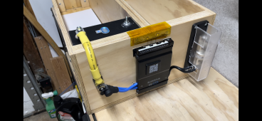
I tested them before putting them online and zero issues. Nite that the JKBMS' come with Silicone with and I used Similar Silicone but lager guage. See Below. * They did not have Blue 4-AWG so I got red, oh well. You may not the ends are different, the B- is sized to connect to the cell and the P- to the 3/8 Terminal Lug leading for the battery pack. All Crimps are done with a Hydraulic Cimper so no loosie goosey there. PS Use only Shrinkwrap with Adhesive. For the obvious potential question 2x7-AWG = 4-AWG so no current capacity is lost.
View attachment 107233View attachment 107234
Still is a safety issue, you fused it for all wires handling the load, but one can fail at a connection, leaving the others to overheat.
Pappion
Retired Engineer Tech
- Joined
- Nov 26, 2020
- Messages
- 552
Victron multiplus 3kw 24v example pdf.
300A fuse, 2x 50sqmm wires, 0-5m cable length.
300A fuse, 4x 50sqmm wires, 5-10m cable length.
They use the same fuse and double up on the wires for longer runs. If one wire/connection goes bad, the other is in fuse limits. Performance takes a hit.
300A fuse, 2x 50sqmm wires, 0-5m cable length.
300A fuse, 4x 50sqmm wires, 5-10m cable length.
They use the same fuse and double up on the wires for longer runs. If one wire/connection goes bad, the other is in fuse limits. Performance takes a hit.
Why would one not just buy the right size wire needed and replace it.? .. why trust someone else’s work… is the crimp solid .?. did they trim some of the individual wires to get it fit.? Was it done only because they had it laying around.? I wouldn’t want it if I had a choice…If you have to have two cables. Each should have its own crimp connector and just stack them. Just because some Chinese battery manufacturer does it doesn't mean it's the correct way to do it.
jim.
There are some cases where you need two wires and you can't use one larger one. Perfect example is if two wires are coming from two different locations but need to land on a post. You still want one lug per wire vs putting both of those wires into one lug.Why would one not just buy the right size wire needed and replace it.? .. why trust someone else’s work… is the crimp solid .?. did they trim some of the individual wires to get it fit.? Was it done only because they had it laying around.? I wouldn’t want it if I had a choice…
jim.
Good point.. good point… .thx..J.There are some cases where you need two wires and you can't use one larger one. Perfect example is if two wires are coming from two different locations but need to land on a post. You still want one lug per wire vs putting both of those wires into one lug.
Swgraham2
New Member
- Joined
- Aug 6, 2022
- Messages
- 12
The double wires with single crimp came with controller that way. I may sever the ends, separate wires then crimp individually with new new lugs. This group is the best.Why would one not just buy the right size wire needed and replace it.? .. why trust someone else’s work… is the crimp solid .?. did they trim some of the individual wires to get it fit.? Was it done only because they had it laying around.? I wouldn’t want it if I had a choice…
jim.
MrThisIsME
Solar Enthusiast
- Joined
- Aug 8, 2022
- Messages
- 500
Bet they are AL and really not worth it least by me,.The double wires with single crimp came with controller that way. I may sever the ends, separate wires then crimp individually with new new lugs. This group is the best.
Ranger Rick
Here comes the sun
It is better for each cable to have its own lug. One multistrand cable is round, but two cables would be in an oval shape and would have less contact in one lug (safety issue. )In some Victron inverters, there are two negative posts and two positive posts for incoming DC voltage. One lug instead of two lugs saves pennies (or more) and less labor (one crimp instead of two =??). I'd convert from one lug to two lugs.My inverter is Renogy 1000W Pure Sine Wave. My battery backup is two12V lead acid batteries in parallel totaling approximately 200 AH. My inverter and cables are take-offs from a "Backroads Overland Co" camper. Apparently, the camper was displayed at trade shows and eventually sold to a customer that wanted an inverter upgrade. I bought the inverter with cables locally off a BROC rep on marketplace for a fair price.
I'm obsessed with learning solar and watching @Will Prowse videos. I can't seem to find why two cables would be crimped in one lug on the WWW.
Squowse is correct that two cables are more efficient than one cable. Using that same theory of increased surface area, making small crosscuts in a busbar increases surface area (like a heatsink).
Not a lug, but same idea.I've never seen any industry standard allow for multiple conductors in a single lug.
@Steve_S can you post literature or some form of evidence to support your claim that multiple conductors can safely be used in a lug that is designed for a single conductor?
MMMm i'm pretty sure the pressure will equilibrate and there will be no problem with the oval vs circular form.It is better for each cable to have its own lug. One multistrand cable is round, but two cables would be in an oval shape and would have less contact in one lug (safety issue. )In some Victron inverters, there are two negative posts and two positive posts for incoming DC voltage. One lug instead of two lugs saves pennies (or more) and less labor (one crimp instead of two =??). I'd convert from one lug to two lugs.
Squowse is correct that two cables are more efficient than one cable. Using that same theory of increased surface area, making small crosscuts in a busbar increases surface area (like a heatsink).
I feel that 2 cables in the same lug will still have less electrical resistance then 2 lugs connected one on each together.
So there is this way :
Or using a butt connector with a 30mm2 on one size and 2x13mm2 on the other side... which i prefer (less interfaces)
Did someone desolder stock cables and solder bigger one on a Jkbms ?
Last edited:
The only advantage to using multiple conductors is flexibility for very short runs and reduced strain on a PC board. Probably the best option is multiple lug like the previous post shows if you have the room. The only problems I’ve seen with multiple wires in the same lug is improper fill/cables sizing and corrosion. The voids/valleys formed by two or more rounds are impossible to seal with adhesive heat shrink alone. What seems to work excellently is a few small beads of electrical grade silicone in the valleys just prior to heat shrinking and wipe off what extrudes. I’ve tried Shoe Goo but it’s not flexible enough to stay attached to a silicone covered wire with hard straining. Never ever use regular silicone adhesive around electrical for sealing out moisture(the stuff that smells like vinegar). That curing agent leaches out for months or more and the vapors are very corrosive to tin, zinc, silver and copper in an enclosed environment.
When I purchased my three OverKill BMS units, their cables were built this way. Both leads were combined into a single lug.I've never seen any industry standard allow for multiple conductors in a single lug.
Similar threads
- Replies
- 3
- Views
- 220
- Replies
- 6
- Views
- 213
- Replies
- 25
- Views
- 954


