diy solar

diy solar

Two Charge Controllers Charging From Opposite Ends?

Joined
Nov 12, 2019
Messages
26
Location
New Orleans burbs
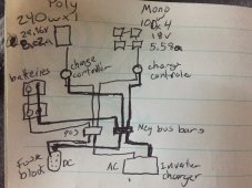
I have one battery bank with six 12v 100ah LiFePO4 batteries. I have two solar arrays (600 watts each) going into two Epever charge controllers. The system works but I'm getting ready to move some things around and add some mini-circuit breakers (replacing older inline audio type) and a DIN strip so I was wondering if I should re-route how the charge controllers charge the battery bank?

Right now, I have both charge controllers going to busbars and then single wires going to the + and - on opposite diagonal ends of the battery bank.
I have a lot of extra wire and was thinking about having one charge controller stay the same and the other go to the opposite + and - diagonals to maybe add the incoming charge more balanced?

I'm guessing it wouldn't hurt either way but I wanted to float the idea.
 
It sounds like you have this set up:
1615221038374.png

I would keep the chargers going to the bus bars, but would look for ways to better balance the resistance to the batteries.

The first and easiest is to do something like this:

1615221258490.png

The above is better, but not perfect.


Without knowing more about your set-up, it is hard to say what the best next step would be. The objective is to balance the resistance from the busbar to each of the cells. There are two complimentary ways to do this.

1) Make the resistance so low the differences don't matter (Use oversized connections between cells)
2) Wire the batteries in a way that balances the resistance.

Ideally, the design would do as much as is practical for both minimizing and balancing the resistance.


One way to balance the resistance is this:

1615222164434.png

The objective of the above is to make the wires going from the bus bars to the batteries *identical* so the resistance is the same. There is a danger here: Just one bad crimp can ruin the balance. (Note: As long as the interconnects are matched, going to opposite ends of two batteries in parallel provides balanced resistance)
 
Would it be a good idea to put circuit breakers between each battery bank and the busbars? Although it would be easy enough to disconnect one of the banks and the other two would still be connected, to double-check charging, resistance, etc. on each bank, right?
 
While I have only two batteries, each one is 280Ah, and each battery has its own leads that go to the the common connections. In my case, the positive wires from each battery first go to a Class T fuse and then to a battery disconnect switch. After the switch, the cables go to the common bus bars where everything else (loads and charges) are connected.

If I were to add more batteries, I would add a common bus bar before the switch to allow all the battery cables to connect to. Each battery would also get its own fuse. I cheated a bit on my system since I have only two batteries.

Circuit breakers to protect the battery cables are not common. As in, it's probably not the right way to do it.
 
Are you doing this setup because of different panels? Would this work for 1 240w Poly panel & 4 100w Mono panels to same battery bank?
 

Attachments

  • IMG-3917.jpg
    IMG-3917.jpg
    251.9 KB · Views: 7
The drawing has 2 separate charge controllers.
My question is will the 2 charge controllers charge the SAME battery bank? Can I use bars as a gateway to merge the 2 charge controllers & therefore having 100% efficiency on 1 battery bank?
 
The drawing has 2 separate charge controllers.
My question is will the 2 charge controllers charge the SAME battery bank? Can I use bars as a gateway to merge the 2 charge controllers & therefore having 100% efficiency on 1 battery bank?
Yes
 
The drawing has 2 separate charge controllers.
My question is will the 2 charge controllers charge the SAME battery bank? Can I use bars as a gateway to merge the 2 charge controllers & therefore having 100% efficiency on 1 battery bank?

Yes to both questions.
 
Back
Top