diy solar

diy solar

Two questions regarding wire sizing from array to controller

JustPractical

New Member
Joined
Aug 31, 2021
Messages
106
I've reached that point in the project where I'm second guessing everything and running out of money. I could use some help with the thinking part.

My ground mount array will be 4640w, 16x290w, Two banks of 4S2P feeding two separate PV inputs on a Growatt 12k. I plan to mount the disconnect on the array, and originally planned for it to also be the combiner – but now I’m seeing things that look like “plug combiners” that might work (I’m not familiar with them – saw them on Practical Prepper.net website). If I was using the disconnect as a combiner, it’s 8 wires turning into 4.

Panels are Q.PEAK 290's Voc=39, Isc=9.63 Imax=9.07. Each bank of 4S2P would then be a max of 157 volts and 19 amps per bank combined.

QUESTION #1: based on the spec sheet of the 290W panel (second column of the attached image) have I calculated these numbers properly?

Battery voltage will be 48V nominal. This is an off-grid system. The array, a ground mount, will be about 90 feet from the house, and then another 40 feet inside the house to the inverter.

Inverter info: Growatt 12kw Inverter - 2x60A 250V MPPT’s (Split phase 120/240) 100A Max Charging Current 7000W max per MPPT

QUESTION #2: I think I can run 12AWG THHN to each bank of the array (so a total of Four 12AWG conductors heading back from the array to the inverter). Yes? I keep trying to use “worst case numbers” for everything, but don’t want to oversize the wire. The wire will run in PVC conduit for most of its length (outside is buried conduit).

Have I missed something? Is there a cheaper or better way? Thanks in advance - this group has been super helpful.
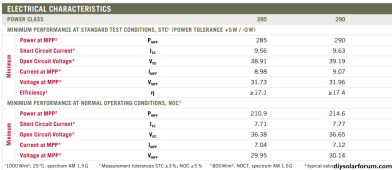
Panel stats small.png
 
12 will work, but you will lose about 10%
I would run #8
Thanks for the advice (and sanity check). I would consider running 8, but 12 is more "available" at work. I was considering doubling up 12's, but that seemed overly ghetto.
 
1) Your solar panel setup is good, you can branch plugs, or y-cables to combine the 2,4 series panel strings, you can also just combine them in the disconnect box. You will also want a disconnect for the PV circuits at the house. If you are in a locality that is under NEC 2020 all PV dc circuits inside the house need to be in metal conduit, NEC 2017 only requires metal to the first disconnect if it's inside.

2) NEC code requires PV wire ampactiy to be at least 1.56 the total Isc, 9.63amps * 2 strings in parallel * 1.56 = 30 amps, so you will need to use 10 awg at least once the 2 series strings are combined. With 10 AWG voltage drop at 150 ft would be 5%, upsizing to 8 AWG would reduce voltage drop to 3%.

If you are running both arrays in the same conduit you will have more than 3 current carrying conductors and will have to derate the amp capacity of the wires. Luckily in your case 10AWG has enough ampacity to handle this derating. so you are still good with 10 AWG minimum

You will also need an equipment grounding conductor running with the PV wires to the arrays this can be a single 10 awg conductor if they are both in the same conduit.
I have questions...:unsure:
1) By "just combine them at the disconnect box" could I just put a ring terminal on each string and put them on the same lug of the disconnect. (Assuming the disconnect is rated for the combined ampacity.)

2) Maybe (assuming I had plenty of 12AWG) might pay to run each string back to the disconnect as 12, combine there, and just run the inside stuff with the heavier gauge. EDIT: Did the math - assuming I had to buy either the 12 or 10AWG, comes out to $40 more to go with the 12.

Derating for conduit loading - now that's getting fancy (I think the individual strands on 12 would also be OK, but I didn't do the math). You will appreciate that I'm putting detactable burial warning tape on top of the conduit route.
 
Last edited:
I have questions...:unsure:
1) By "just combine them at the disconnect box" could I just put a ring terminal on each string and put them on the same lug of the disconnect. (Assuming the disconnect is rated for the combined ampacity.)
That would work, If you want to put 2 wires in the same lug you should verify that the lug on the disconnect is rated for 2 wires of the size you are using.
2) Maybe (assuming I had plenty of 12AWG) might pay to run each string back to the disconnect as 12, combine there, and just run the inside stuff with the heavier gauge. EDIT: Did the math - assuming I had to buy either the 12 or 10AWG, comes out to $40 more to go with the 12.

Derating for conduit loading - now that's getting fancy (I think the individual strands on 12 would also be OK, but I didn't do the math). You will appreciate that I'm putting detactable burial warning tape on top of the conduit route.
You can run each string on 12 AWG, and you'd still be ok with all 8 conductors derated to be in one conduit(along with a ground)
 
If your equipment will allow you to run the array as 8S2P from the combiner box, 12 gauge will give you 3.5% voltage drop.
 
I have questions...:unsure:
1) By "just combine them at the disconnect box" could I just put a ring terminal on each string and put them on the same lug of the disconnect. (Assuming the disconnect is rated for the combined ampacity.)

2) Maybe (assuming I had plenty of 12AWG) might pay to run each string back to the disconnect as 12, combine there, and just run the inside stuff with the heavier gauge. EDIT: Did the math - assuming I had to buy either the 12 or 10AWG, comes out to $40 more to go with the 12.

Derating for conduit loading - now that's getting fancy (I think the individual strands on 12 would also be OK, but I didn't do the math). You will appreciate that I'm putting detactable burial warning tape on top of the conduit route.
NEC does not allow you to parallel strings smaller than #4 and the equipment would need to be rated for installing more than one conductor in it...

And if you did, you would need to fuse each conductor for 20A all of this will introduce voltage drop.

I understand the desire to use conductors you already have, but it would be best to just run #8
A spool of #8 thwn is only $260.
You can use the #12 for the grounding conductor. Since the load is below 20A
 
If your equipment will allow you to run the array as 8S2P from the combiner box, 12 gauge will give you 3.5% voltage drop.
Inverter info: Growatt 12kw Inverter - 2x60A 250V MPPT’s (Split phase 120/240) 100A Max Charging Current 7000W max per MPPT

If I ran 8S2P, that would be 312 Volts, 19 amps, and about 4640 Watts. That's an idea, but I don't think the 12awg will take that.
I broke it up because the array will get some partial shading, so I thought smaller "banks" within the array would cope better with the shade.
QUESTION #3: Is my thinking regarding shading and smaller arrays accurate? 8S2P will be easier to wire and get disconnects for, so I'm more than good doing it that way if it makes no difference.
You could use a separate high voltage charge controller. I don't use the MPPT's in the LV6548's, I installed a pair of EG4 100AMPPT's that are rated to 500V.

You can't run 8S2P at 312V for the Growatt 12Kw inverter as the max VOC is 250V. Exceed 250V and it will have magic smoke come out.
 
NEC does not allow you to parallel strings smaller than #4 and the equipment would need to be rated for installing more than one conductor in it...
Is there a PV specific allowance in 690?

310.10(H) as I read it says 1/0 is the minimum; with an exception to use smaller to reduce voltage drop but NOT increase ampacity. I don't see text here that says you need individual 20A fusing in this case.
 
A consideration with #12. If you have a situation where all the panels get wrecked, and in the future only M10 and M12 panels are available locally, you cannot put them on #12 (max ISC 12.8A). #10 (max ISC 19.2A) is able to handle up to M12 cells (17A ISC I believe) and maybe even a size above that.
 
Is there a PV specific allowance in 690?

310.10(H) as I read it says 1/0 is the minimum; with an exception to use smaller to reduce voltage drop but NOT increase ampacity. I don't see text here that says you need individual 20A fusing in this case.
Oh, the fusing would be instituted if smaller wiring was used due to the inability of the single conductor to handle the combined load. I doubt it would be an issue in this case, but it is something to consider.
 
Oh, the fusing would be instituted if smaller wiring was used due to the inability of the single conductor to handle the combined load. I doubt it would be an issue in this case, but it is something to consider.

Hmm actually that exception is pretty restrictive (this is Article 310, I haven't looked into Article 690 on parallel, partly b/c I think small conductor paralleling is janky)

1: Conductors in sizes smaller than 1/0 AWG shall be permitted to be run in parallel to supply control power to indicating instruments, contactors, relays, solenoids, and similar control devices, or for frequencies of 360 Hz and higher, provided all of the following apply:
 
You could use a separate high voltage charge controller. I don't use the MPPT's in the LV6548's, I installed a pair of EG4 100AMPPT's that are rated to 500V.

You can't run 8S2P at 312V for the Growatt 12Kw inverter as the max VOC is 250V. Exceed 250V and it will have magic smoke come out.
You are 100% right. Got focused on the current and wattage and forgot about the voltage.
 
NEC does not allow you to parallel strings smaller than #4 and the equipment would need to be rated for installing more than one conductor in it...

And if you did, you would need to fuse each conductor for 20A all of this will introduce voltage drop.

I understand the desire to use conductors you already have, but it would be best to just run #8
A spool of #8 thwn is only $260.
You can use the #12 for the grounding conductor. Since the load is below 20A
If I parallel them at the array with a combiner (or a plug connector) then 10AWG is OK for each 4s2p bank, yes?
 
I'm not sure the parallel conductor rules in the NEC apply here, as only one side of each wire run is connected in parallel. There are 2 separate sources, with separate wire runs, that are joined at one point. Not the normal parallel conductor setup where both sides of a run are connected together.
 
Back
Top