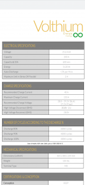
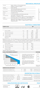
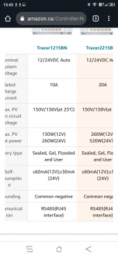
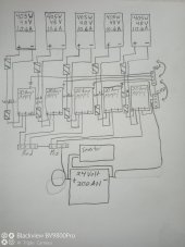
I want to know if the 405 watt bifacial panels are a good fit for the epever 20 amp controller at 24 volt. I know will said the panels can push 500 watts and the controller can handle that. Their under 11 amps so the controller can handle that. And thier around 50 volts the charger can handle 150/138@25°c. It can handle that. I know it has room for the 25%increase all across the board. So I know it can handle it. Now, it won't put out more amps than the panel is rated for will it, like if the voltage drops. I want to install up to 5 of these combinations together (5×1+1) but if the amperage is going to be greater than 10 amps per controller than it'll be too much. The battery recommended charge rate is 40 amps and max is 150amps. I was ain Ng for around 50 collectively and hoping for some losses in connection's. Is this functionable ? What arey possible max amperage outputs from my controller ? Thanks for anyone's knowledge.


You are using an out of date browser. It may not display this or other websites correctly.
You should upgrade or use an alternative browser.
You should upgrade or use an alternative browser.
Underpowering controller ?
- Thread starter MrAubin
- Start date
MichaelK
Solar Wizard
No, this is NOT going to work. The 20A rating is for the output to the battery, so assuming your battery charges at >25VDC, the most you could utilize is 20A X 25V = 500W of panels. So, you can NOT use more then one of these 405W panels.
In the real-world, you are really not likely to ever see 100% of rated output, so you can typically include a fudgefactor of 85% in your math. That is, expect your panels to only put out about 85% (0.85X) of the wattage they are rated at. One 405W panel would put out (405W/25Vcharging) X 0.85X = 13.77A. Two of them would already equal 27.5A.
Now, if you want to charge the battery with at least 40A, you need at least a 40A controller. Let's say you use four of those panels. The math is {(405W X 4 panels)/25V charging} X .85 = 55Amps. You had better get at least a 60A controller. Look at Epever's Tracer 6420 controller. That can handle 200Voc. For a good safety margin though I'd wire the panels in a 2S2P configuration.
If you really want to install five panels, what you can do is wire one panel only into the 20A controller and connect that to the battery bank, and then wire the other four panels to a second Tracer 6420 controller that's attached independently to the same battery bank. That would then give you 13.77A + 55A to your batteries.
To do the math properly, and make sure that the Voc is never exceeded, we will need to know the exact specifications of these panels. There will be a label on the back of each panel which documents Vmp, Voc, Imp, and Isc. Please provide those numbers.
Not at all, I want 5 of 1 panel hooked up to its own charge controller and will says as many as you want without exceeding the battery charging amps. So I am planing multiple 20 amp epevers each with a single panel. It's a 24 volt set up and the panels are around 50 volts not 25. Should I not only be getting around 8 or 9 amps from the controller? I read that the controller has to drop the 50 volts to 24 volts and that would increase the amperage. I hope that person was wrong. I want to get no more than 10 to 12 amps from my 20 amp controller 4 or 5 times. I'll get the paperwork here together and write battery specs and panel specs and controller specs.
MichaelK
Solar Wizard
Sorry, I didn't understand what you were saying at first. Your English writing skills are a bit hard to comprehend. Yes, I suppose hooking up 5 charge controllers to 5 individual panels will work, but it seems absurd to me that you'd want to do things that way? One of the single best reasons to use a MPPT controller is that you can wire panels in series to reduce voltage drop, and power loss because of wire resistance.
Is this because you have a source of cheap or free 20A controllers? On Ebay, I see the 20A unit selling for ~120$US right now. But the 30A version of the same controller is only 146$US. If you bought the 30A instead of the 20A you could wire two parallel or serial panels per controller, and save 26$ with each connection. Assuming they are 90% efficient (rare) then the math would be {(405W X 2 panels)/25Vcharging} X 0.9efficency = 29A
What is your reasoning behind wanting to wire 5 panels to 5 controllers?
25V is the CHARGING voltage during the bulk phase, which will gradually increase as the battery becomes fully charged. It will max out at ~29V, depending on your controller settings. You don't have 50V panels. Their Vmp is 40V, with a Voc of 48V.
Well I was going to start with 1 panel and 1 controller on a battery because I can't afford to buy everything at once. I ordered the appropriate charger for the panel I selected and went for the panel. Apparently you have to order minimum of 4 panels. So I might as well get a fifth for losses. And I honestly like the look of lots of devices and the look of the aluminum tracers. I have some wire coming 1/0 for main cables not sure if I can manage 6 awg cable into the 8 awg terminals I'm having trouble finding good enough quality 8 awg. And can't I hook up 2 of these panels to the 20 amp charger if at 400 watts at 48 volts is only 8.33 amps so 2 in series would be 16.6 amps or plus 25% equaling what 21 amps so no would need like 380 watt panels for that. Also the bifacials if reflected from behind can push 500 watts Will said that's close to the max on a 20 amp tracer max on 24 volt system. I was trying to plan everything to stay under maxes. So 5 tracers pushing 8 amps gives me my 40 amps charging to my battery or super close to. I love wiring, but am having to relearn all the math. Thanks for your time and thoughts.
Sorry no if I hook up a second panel series to the controller I'll get 96volts which the controller can handle not 21 amps. So if in another year or two I could get 5 more panels and double my available collection. Also if I move I could collect from many different angles of sun throughout the day.
MichaelK
Solar Wizard
Don't accept hearsay as fact. The best way to determine the real output of your panels is to actively measure it yourself. As a general rule of thumb, panels usually never produce more than 85-90% of their label output. That is because their rating is determined in an artificial sunlight chamber with artificial sun at exactly 1000W/square meter, and at a temperature of exactly 25degrees C. In the real-world, output is usually always somewhere half-way between the STD rating and the NOCT rating. So, you add that as a fudgefactor (FF) to compensate.
To really quantify what you are working with, I recommend very single solar producer should have a good clamp meter. I always recommend this one. In does both AC and DC volts, AC and DC amps, AC inrush amps, resistance, and frequency.
https://www.ebay.com/itm/323819337307?epid=710119969&hash=item4b6522f65b:g:oMcAAOSwhOVXc-Bm
That being said, I would still not buy the 20A controller, I'd get at least the 40. The math works out to be (405W X 2panels)/25Vcharging X 0.9FF= 29.2A. A FF of .9 is being very cautious. I usually use .85. So, with the 40A controller, you get the benefit of wiring two panels in series to get 80V so your power loss through wire resistance will be lower. You also get the benefit of using thinner wire because of higher voltage. That means 10 gauge wire to the controller.
Use this wire gauge table to determine the size of wire you need. Let's say you wire two panels in series, and you have 10A at 80V. Looking at the chart, you can see that 10 gauge will safely handle 30A. Suppose you wire a total of four panels in a 2S2P configuration, and used a higher capacity controller. That would be a total of 58A at 80V from the controller to the batteries. Looking at the chart, 4 gauge would safely handle that much. So, 4 gauge from the controller to the battery. Your battery to inverter connection is where you want really heavy wire. Let's say you have a 4000W inverter powered at 24V. That's 4000W/24V = 167A. I'd use 4/0 wire for that.
Last edited:
Similar threads
- Replies
- 7
- Views
- 245