There are a few possibilities at play here.
One test to do, is to change the location of where it is connected on the DC Bus Bars. Assuming a 4-bolt busbar and you packs connected to Bolts 2 & 3 and the main DC wire to SCC/Inverter on Bolt-1, swap the bolts between packs, or put Pack-1 on Bolt-1, SCC/Inverter on Bolt-2 and Pack-2 on Bolt-3. Do this on both + & -. Sounds silly but you'd be surprised. IF this makes no change then that potential problem is eliminated leaving ONLY the "pack" internals.
Pack Internals.
A BMS can be a problem, but most often it is a matter it works or it doesn't, very rarely anything else UNLESS there is bad software configuration but that would be fairly obvious quickly into the troubleshooting.
* You did not mention Type of BMS, Type of Cells, IF the BMS is a SmartBMS which can be accessed via software/bluetooth/wifi etc.
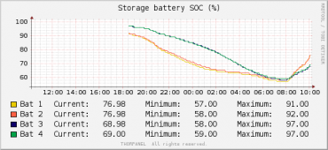
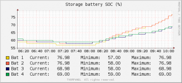
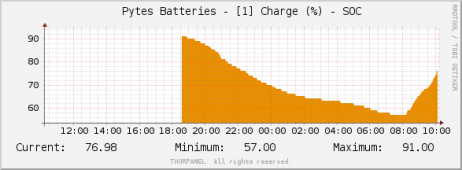
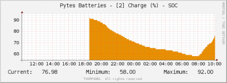
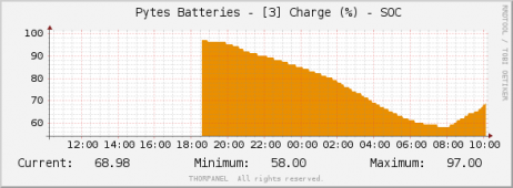
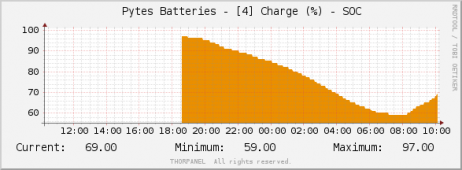
I think the one battery has something wrong with the cells, possibly resistance issue?
- Cells known as "Runners" are not uncommon with Grade-B, Bulk and lower graded cells. They can either reach a full SOC ahead of the other cells or reach Empty ahead of the others. In such an instance the BMS would trigger a Cell Protection cutoff and cease charging or discharging. Proper Grade-A Matched & Batched cells do not suffer such issues typically but these of course are most costly.
They are tough to figure out once inside a built pack. If the pack uses screws/bolts for the busbars or if welded makes a difference. A device like the Yaorea 1035+ battery tester can read the voltage & Internal Resistance of the cells. Each cell would have to be charged to the same voltage IE 3.400, allowed to saturate till taking less than 2A, allowed to settle for 1 Hour and test. Then discharge cells to 3.000 and retest again for IR. IF all good the cells should be within 2.mOhm
- Connection failures such as loose busbars, wires etc can also result in faulty readings which show up as capacity losses. Loose connections will Generate Heat ! This can be extremely hazardous leading to fire. Checking all the connections, busbar attachments, BMS Harness etc is important. The BMS Harness could also be faulty (hi resistance or loose) sending false signals resulting in BMS trips, it doesn't take much.
NOTE for SmartBMS.
If you have a smartBMS in these packs that can be monitored then you can watch both packs during the charge cycle. Normal operation will see near identical input voltage to both packs (it does float 0.0## volts between packs) and similarly with the Amps being taken which will also float a "slight bit" as the different cells take the charge and if there is a balancer at work as well. This is normal & expected behaviour but IF you see one pack taking less Amps or Voltage and you look at the cells and one or two are farther out of synch (especially noticeable above 3.375 or below 2.900 if discharging) that is an Indicator of a weak cell or likely "runner". Again a Loose or Dirty Busbar Connection at that cell may also be a culprit.
Loose & Dirty bus bars are the bane of systems, especially for the DIY scene, less so for professional builders. "Professional Builders" is subjective... BattleBorn, SimpliPhi, Relion, Victron, CATL, LG etc = Pro Builder's. Many "PreBuilds" can be "Dubious" if coming from who-knows-where-shops. Then you have companies like SOK, EG4 who are striving to take market share with good quality @ reasonable prices "pro".
Hope some of this helps.