Offgridiot
New Member
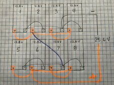
Hello all. I’m in the process of upgrading my off grid system, starting with the replacement of my old FLA battery bank. I have a MagnaSine 4024 at the heart of the system, so I’m committed to 24 volt configuration. I’ve bought 8 Power Queen 12.8V 300AH LiFePo4 units (for some admittedly questionable reasons but here we are) and am planning to set them up as two parallel strings of 4 each, and series those together for 25.6 Volts, based on advice from someone on another forum. I tend to torture myself with overthinking these things, and this time is no different. So, I was led to the website smartgauge.co.uk where I found that the best way to wire multiple batteries together in parallel is with the ‘cross diagonal’ method. I took that as gospel and proceeded with my plan. I bought a length of 2/0 cable, and cut it into equal length pieces for the interconnects. All good. Now, I’m looking at buying a balancer to go between the series connected strings, and here’s where the overthinking/second-guessing starts. Every balancer setup I’ve found pictures of has the batteries wired differently than my plan (they either have all 4 parallel units bonded with a bussbar or post (as opposed to cross diagonal) or they have four sets of 2 units in series to get the 25.6V ), and this has me wondering if I’ve been led astray.
Thank you in advance for any and all help
- After having cut and crimped and heat-shrinked all the interconnects for my cross diagonal setup plan, I’m not sure I’d be able to use them in a different setup. If there are strong opinions from you experts about this, I’m open. Should I have my bank set up the way I’m seeing on the Victron balancer diagrams?
- I’m seeing diagrams where the balancer wiring has the common terminal wired to the midpoint of the series connector. Is that literally where this should be tied in? Should I have two cables end to end for this so that I can tie in that ‘common’ balancer wire equidistant from each parallel string? Or is it fine to have it right at the one battery terminal?
- Victron seems to be a solid brand choice for any electronic component. Their balancer though, seems relatively simplistic and underpowered (only 1 amp balancing power, and no voltage display)compared to a few others I’ve seen (5 amps balancing power, and voltage display for both sides). Opinions/recommendations?
- The BMSs in my batteries are 200 amp. I bought 200 amp MRBF fuses for each positive terminal. Am I good there?
- My batteries don’t have any Bluetooth capability but I’ve been looking at trying to add that functionality. I’m eyeing the Victron SmartShunt 500A smart battery monitor. There’s already one non-Bluetooth shunt in place in my system for the MagnaSine battery monitor (which I kinda hate), but it’s installed inside an e-panel metal enclosure, and if I was to replace it with the new Bluetooth shunt, the signal would likely have a hard time getting in and out of the enclosure). Would there be any problems adding a second shunt to the system?
- I was thinking of installing a voltage meter on each battery. I understand that all of the batteries hooked together in parallel will automatically equalize, and the whole purpose of the balancer is to work to do the same but I was thinking that it might be possible for the BMS in any unit to shut down that battery, and it might not be immediately obvious something was wrong. I like the idea of being able to glance at all the individual battery voltages for peace of mind. Or is that a scenario that the alarm on the Victron balancer would let you know about, when one of the parallel strings all of a sudden has a different capacity?
Thank you in advance for any and all help