diy solar

diy solar

Van electrical update, 12v 10kwhh+, solar & alternator - Please review.

What is the ah rating of each battery?
It's Lishen 272AH cells. 150A JBD BMS.

What exactly is a discrete fuse?

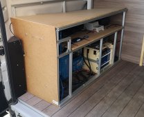
That's my current install.

1648505958829.jpeg
1648506001621-jpeg.89055


I was a bit in a rush last summer. So I did a v1 with only 1 pack.
But I would like to use the AC inverter for bigger load and putting 4 packs in this space seemed complicated so went with 3 instead.
 

Attachments

  • 1648506001621.jpeg
    1648506001621.jpeg
    244.3 KB · Views: 31
To do it properly you need to know your daily Wh usage so you can properly size your battery and solar. Looking into the biggest loads is very useful too. It can help you to decide to avoid such loads as well as determine what size inverter you need.
I understand your logic.

Last year when I did my first. I documented my journey here.

Wasn't getting any answers so I thought about doing an electrical oriented, simpler to follow topic.
 
It's Lishen 272AH cells. 150A JBD BMS.

What exactly is a discrete fuse?
A stand alone fuse as opposed to a fused position on a busbar.
A class-t fuse in its own holder is the former, the lynx distributor is the latter.

The dead short ampacity of those cells is more than high enough to call for a class-t fuse.
 
For the POS battery busbar, I was thinking of something similar to this in concept.
1648566423859.png1648566477702.png

When I looked at the lynx distributor, each busbar is 8mm by 30mm but they are rated for up to 1000A.
But when I look at online calculator for busbar ampacity, this width and height results in 288A max.

For my system, I would need a 500A busbar.

Is it because not all the load goes trough the busbar at the same spot?
1648566692926.png


1648566201773.png1648566251860.png
 
For the POS battery busbar, I was thinking of something similar to this in concept.


When I looked at the lynx distributor, each busbar is 8mm by 30mm but they are rated for up to 1000A.
But when I look at online calculator for busbar ampacity, this width and height results in 288A max.
I was actually looking at the same thing this morning.
Those busbars are 5/16" by 1 3/16"
Using the 1/4" by 1 1/2" thickness I get 564 or 572 amps depending on their orientation.

It depends on how much temperature rise you are willing to accept but the lynx distributor busbars are massive and overkill for 500 amps.
I expect they will pull heat out of the cables attached to them.

For my system, I would need a 500A busbar.
If you need 500 amps you should go to a higher voltage.
Here is my math...
2400 ac watts / .85 conversion factor / 12 volts low cutoff = 235.294117647 service amps
235.294117647 inverter service amps + 80 dc distribution amps = 315.294117647 total service amps
315.294117647 total service amps / .8 fuse headroom = 394.117647059 total fault amps

Is it because not all the load goes trough the busbar at the same spot?
AFAIK the ampacity of a busbar is the based on height and width not length.
 
Last edited:
Those busbars are 5/16" by 1 3/16"
Yes, that's the same I "measured" on the cad model. And later found out in the specs ^^
It depends on how much temperature rise you are willing to accept but the lynx distributor busbars are massive and overkill for 500 amps.
I expect they will pull heat out of the cables attached to them.
1648642325448.png

I compared two high power busbars.
1648642490705.png

1648642520346.png

But when I compare the cross section, the bluesea is beafier and is "only" rated at 600A.
But bluesea states "continuous".

Unless the 1000A rating for the Victron is in total. 500A for each busbar?
 
Unless the 1000A rating for the Victron is in total. 500A for each busbar?
This is the most directly comparable Bluesea busbar.

The dimensional drawing doesn't seem to have the dimensions we seek.
To use this as a fused busbar you need to use this bit
They are limited to 300 amps.
 
The dimensional drawing doesn't seem to have the dimensions we seek.
To use this as a fused busbar you need to use this bit
I took only these 2 models as examples because I couldn't figure out their amps rating based on their cross section.
 
To use this as a fused busbar you need to use this bit
They are limited to 300 amps.
From what I remember from my research back then, aren't MRBF less suited for lifepo4 batteries because of a lesser AIC / Interrupt Capacity ?
 
From what I remember from my research back then, aren't MRBF less suited for lifepo4 batteries because of a lesser AIC / Interrupt Capacity ?
A Class t can break ~20000A @ 125V DC

In the last year or two I saw a plot of a dead short of an LFP cell.
Unfortunately I've not been able to locate and I have looked.
The plot showed that the cell generated ~100C for some seconds before the vents popped.
My guess is that by the time you make a 4s battery the resistance will limit the dead short current to ~50C.
That would be ~5000 amps.
An MRBF fuse can break ~10000A @ 14V DC.
 
I decided to go with class T fuse for each battery.
Here is the latest diagram revision.
1648744397444.png
 
FWIW,
I’ve got (3) eg4 12v rack packs in a single string.
I used MBRF fuses on each positive and a class t at the end where the main 4/0 positive connection to the bus bar lands on the pack.
It’s not as compact as I’d like but it was easier than trying to actually use class t fuses on each pack.

You need to really reconsider running each battery separately, I don’t see any advantage and you are spending good money on a bunch of class t that aren’t really needed if you have one at the landing spot.
 
I’ve got (3) eg4 12v rack packs in a single string.
In a vehicle mounted system?

You need to really reconsider running each battery separately, I don’t see any advantage and you are spending good money on a bunch of class t that aren’t really needed if you have one at the landing spot.
From what I read in this forum and sailing forums.
Tldr: Class T is currently recommended for subdivided LiFePO4, under ABYC TE-13, will become a requirement when TE-13 becomes a full blown standard. Subdivided means the individual batteries each get a fuse so as not to exceed AIC of a single bank fuse.
 
In a vehicle mounted system?


From what I read in this forum and sailing forums.
Tldr: Class T is currently recommended for subdivided LiFePO4, under ABYC TE-13, will become a requirement when TE-13 becomes a full blown standard. Subdivided means the individual batteries each get a fuse so as not to exceed AIC of a single bank fuse.
Yes, I have them mounted in a small rack in the basement bays.

You should have a class T on the Positive connection from the battery bank to the main bus bar, but I don't think you need one at every battery. I've got these on each battery positive and then a class T where the positive connection leaves the pack heading to the bus bar.
 
Back
Top