diy solar

diy solar

Victron Multiplus II 2X120, recommends 2X1/0 gauge

Overtaxed

New Member
Joined
Nov 13, 2023
Messages
83
Location
Gaffney, SC
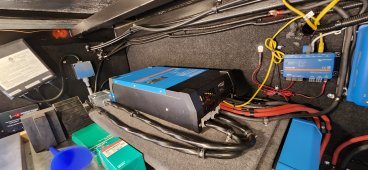
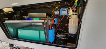
I'm installing a Multiplus II into our RV and am wondering if there's a way to save a spot in my Lynx distributor by crimping 2X1/0 gauge wires into a single 4/0 gauge lug. The Multi is strange in that they actually ask for two runs, dual 1/0's for the length we have (<5 feet). I have no problem doing it, have the wire, but would prefer it if I could put the entire inverter on a single lug of the Lynx distributor; the only way I can think to do that is to crimp both of the 1/0's together into a 4/0 lug. The cross sectional area looks right, and a test fit seems promising, just wondering if anyone has ever done this/recommendations?

It's really strange they specify a 2X connection. Doubled up wires, especially low voltage, can introduce unbalance if everything isn't exactly the same. Also, each of those wires is fused, guess both should have a 100-130A fuse, but, again, any imbalance, you'll blow a fuse if you're under full load.

Thank you for any suggestions/help!!
 
Is this a 12v inverter? 24v or 48v?

What battery chemistry are you using?
 
12V inverter. Here is the manual and the specific call out to use parallel cables.

0 – 5 m***​
2x AWG 1/0​

The batteries are lithium, 230AH with a 200A BMS:

The device actually is perfectly setup to take dual cables, there are two studs for positive and negative, right next to one another. That side is easy, I'm just not sure how to do the other side on the Lynx the best way. Since they are parallel runs, seems they really should be on a single lug/fuse, however, there's no way to get two lugs of 1/0 on the same stud in the Lynx.
In one of the Victron schematics they show the two positive cables going to a switch to turn off power to inverter and then only single cable going from switch to the Lynx.
 
In one of the Victron schematics they show the two positive cables going to a switch to turn off power to inverter and then only single cable going from switch to the Lynx.

Well, guess I could do that. Take 2X1/0 right up to the Lynx, land them on a switch (or a bus bar) and then 4/0 up to the Lynx? That just doesn't seem to make a lot of sense, why not just run 4/0 all the way?

2 1/0's, if I'm reading right, have nearly the same volume as one 4/0. Can carry a bit more current, but that would seem to indicate that you could crimp them into a 4/0 lug (they would physically fit, if it's a good idea or not, that's what I'm trying to figure out!).
 
Is there enough room to get a 4/0 in the Multiplus? On my Quattro 5kVA 2/0 barely fit in there.
 
Is there enough room to get a 4/0 in the Multiplus? On my Quattro 5kVA 2/0 barely fit in there.
I didn't try, but it appears, with the right lug anyway, that you could make it fit. I've seen pictures of the Multiplus II with 4/0 wire in them, so, apparently there's some way to make it fit?!

On the other side, the Lynx can take a 4/0 connection, so no issue there.

I'm just trying to save the space in the Lynx and put the entire Multiplus under a single fuse; which is why I was thinking of crimping the 1/0's together in a 4/0 lug and dropping them combined on the Lynx and then up (separately) to the Multiplus. I know they'd have to be exactly the same length, and the Multiplus end, I'd go back to 2 1/0 lugs, just combining them on the Lynx side.
 
Are you using the lynx power in or distributer?

Also I’d be cautious of narrow 4/0 lugs that “fit” the MP. Just because it fits, doesn’t mean it’s the best set up.
 
Last edited:
Are you using the lynx power in or distributer?

Also I’d be cautious of narrow 4/0 lugs that “fit” the MP. Just because it fits, doesn’t mean it’s the best set up.

Lynx distributor up to Multiplus II.

I mean, this seems a little silly. Isn't this something that people do all the time (wire up a Multiplus to a Lynx)?

Seems like this should be dead simple, use this lug, this wire, etc.

If I go down the route of 2X1/0's on two different spots on the Lynx distributor, any idea on what the fuse sizing should be on each slot?
 
Fusing is always for conductor . .

Also you’re precious statements of parallel causing an imbalance is a bit odd. For this case if one conductor sees 10% current than the other it’ll only reflect in slightly warmer but the 1/0 is still well within its limits.

IMO the double conductor on the 12v systems (no double conductor requirements on 24 or 48v) is for voltage sag of FLA more than thermal concern of the conductor. This voltage sag is so critical to manage on 12 FLA systems as the FLA voltage at the battery terminals dramatically react to increased demand.

Voltage sag isn’t that big of an issue for your batteries.

If it were my system is wire it with one run of 1/0 and notice any issues, heating, voltage drop and if need be add a second run as the directions state.
 
Well, that's kind of good news, my runs are very short, probably no more than 6-7feet of cable (round trip) total between the batteries and the inverter. They are right next to one another; Lynx power in, 4/0 to a shutoff, 4/0 from the shutoff to the Lynx distribution, then about a 2 feet of wire up to the inverter. It's a short path, which should help.

I'm going to give the "double crimp" a try, see if it looks acceptable to me/mechanically secure. Figure it's worth the 2 bucks to see how it looks.
 
Well, that worked better than expected. I crimped both 1/0s into a 4/0 lug (link below for the exact lug I used). I did the first one as a test; cut it open, and was very happy with what I found. Basically a solid mass of copper, no pockets of air anywhere that I could find.

So, after the test, I cut 4 1/0 wires exactly the same length, and, on one end, crimped both together into a 4/0 lug. I then used 4/0 heat shrink on the resulting mass of wires, and then taped it about 3 inches down the wire to prevent them from coming apart. On the other end, I just did 1/0 crimps to go into the Multiplus.

Haven't fired it up yet, but, after seeing the tear down results, I'm pretty confident this is going to work just fine. I was able to get the wires into my Lynx, but I offset the postitive and negative to give myself some room.

Wish me luck!!

 
Last edited:
Final update, working very well. I clamped an amp meter and it appears that the load between the two wires is nearly identical with a signficant load (interestingly at lower loads, there's about a 10% variance between the two wires). Crimped both to one 4/0 lug, then taped it back about 6 in, then put a 4/0 heat shrink over the whole thing. I was able to get them on the Lynx distributor but staggered them, put the positive on one post and the negative a few posts away to keep it from being too much to get the cover back on. Not sure this is the "right" way to do it, but it seems to be working well, thank you for the help!
 

Attachments

  • 20231120_155446.jpg
    20231120_155446.jpg
    647.2 KB · Views: 20
  • 20231120_155518.jpg
    20231120_155518.jpg
    466.5 KB · Views: 19
  • 20231120_155526.jpg
    20231120_155526.jpg
    452.3 KB · Views: 20
Back
Top