diy solar

diy solar

Voltage drop between panels and Charge Controller

The voltage coming from the panels will always be more than that from controller to battery. With same size wires on both ends you will lose less if you make the wire that is lower voltage shorter, so make the wire from controller to battery shorter if you can rather than the distance from panels. You can move it closer to panels but will likely need to consider upgrading size of wire that runs from scc to battery bank.

Only with MPPT. PWM panel voltage is same as battery voltage. It's how they work.
 
You know it really is a shame that the folks who sell this stuff don't offer design assistance for tech support. People have to get online to a DIY forum to find out how to hook stuff up? Maybe I'm getting old, but I remember when people behind the counter used to help you out with that sort of thing.
I agree and some places you buy a whole system or with a significant purchase or upgrade from their previous sell to you will. ALTE and Wholesale solar come to mind at least I think they do. Probably a lot dont because either they dont know or are not capable of doing so or if they know they dont have a good program to print and send to you.
 
You know it really is a shame that the folks who sell this stuff don't offer design assistance for tech support. People have to get online to a DIY forum to find out how to hook stuff up? Maybe I'm getting old, but I remember when people behind the counter used to help you out with that sort of thing.

You get what you pay for. HD can't provide detailed technical support anymore than Walmart can on most retail products they sell. If they could, they'd have to charge more.

I suspect the time you remember is before one could even consider doing DIY solar. :)
 
So, where I live, 18mi NW of Portland Oregon, Sun is a premium. 1450ft elevation and it snowed off and on today. And then because I live in the woods on 5 acres of of land, and area where the sun shines, when it is out, is a premium. I have one place to position my panels. 100ft straight out from my front door. I will need to have the charge controller (MPPT), the batteries, and the inverter 100ft from the panel array, in my garage next to the load center. I plan on using #6 copper for the run. I am hoping the drop will not be significant. As I have been reading this thread here, the GRID power has gone out twice, for just a few minutes, but it does this all the time. Not uncommon to be out for days though. Need solar for basics. Lights in the house would be nice.
For 100 feet You may well be able to use 8ga or 10 ga wire depending on the volts and amps being conducted. Even with 10 ga wire and 18 amps and 120 volts you only have 3% loss with 6 average rated 300 watt panels in 3s2p arrangement but using this voltage drop calculator

Of course if you use say say 18 of the same panels and combined them then sent to inverter you would have something more like this

This is an advantage of having an inverter able to accept high pv voltage then you could put 9 of the same panels in series and combine 2 strings for a 9s2p configuration and get calculations like this

Thats a huge difference in simplicity and wiring cost about $45 for 10ga THHN vs $150 for 6awg THHN approximately. If you have 2 strings of the same panels for 36 panels in all that would be saving around $200.
 
You get what you pay for. HD can't provide detailed technical support anymore than Walmart can on most retail products they sell. If they could, they'd have to charge more.

I suspect the time you remember is before one could even consider doing DIY solar. :)
Yep just like many Auto parts stores and Plumbing supply houses etc but they are usually much better than solar equiptment suppliers.
 
When I go to the hardware store and need help, I look for the old guys. No pimply faced high schooler is going to have a clue.
 
I think you need to be more careful with your terminology here! I think what you are trying to say is wiring is rated for high voltage (ie: 600V), not high amperage. You need to be careful when expressing limits to new people. Nobody here is likely ever to even see wiring that could handle 600amps.
Sorry, It was a typo, Wire size is rated in the amperage they can carry - for example, a 14 AWG is rated for 15 amps. As a retired Electronic Engineer for 30 years, I forget my use of terminology can be unformular to newbies.
 
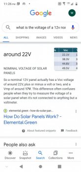
Disagree. 12v panels typically run around 18 to 20 volts, it has to be higher otherwise no battery charging would occur.
Ok, I feel much better knowing it's all MPPT controllers/inverters that have that voltage differential. However, I only see it will what I consider a large load. In my case, it was a load of 900 watts. At 200 watts load, I don't see any difference in voltages.

With respect to my panels, they are rated at 39 ocv at 9 Isc. But because of the angle of the sun with respect to my panels (winter time here) all I'm getting is 34v and 7 amps per panel. The panels are in parallel for the moment. Next week I will put them in series and run testing and see if it buys me anything.
 
Disagree. 12v panels typically run around 18 to 20 volts, it has to be higher otherwise no battery charging would occur.

Wrong. You disagree because you don't know how PWM works. PWM works by effectively shorting the panel to the battery. Current flows from the panel and battery/panel voltage rises in step with each other. Any measured difference is due to wire/SCC resistance.

The fact that PV voltage and battery voltage are the same with PWM controllers has been mentioned on this forum dozens of times. It's a key factor in establishing the fake "MPPT Solar" charge controllers are actually PWM.

MPPT is actually a DC-DC converter, so the panel voltage will be higher than the battery.
12v panel is a nominal label, meaning industry lingo for panels that go with 12v system, not the actual voltage. 12v panels range anywhere from 18v to 20v. Look on the back of any solar panel sold for 12v systems.
 
12v panel is a nominal label, meaning industry lingo for panels that go with 12v system, not the actual voltage. 12v panels range anywhere from 18v to 20v. Look on the back of any solar panel sold for 12v systems.
You lecturing snoobler about such basic stuff is amusing.
Snoobler has a vast range of knowledge about solar so go read a few of his 5,000 plus posts on this forum before you embarrass yourself.
 
12v panel is a nominal label, meaning industry lingo for panels that go with 12v system, not the actual voltage. 12v panels range anywhere from 18v to 20v. Look on the back of any solar panel sold for 12v systems.

With a PWM controller. All attached solar panels are at battery voltage. Period. You could put a 24V panel on a PWM, and it will be at battery voltage.

This is a very basic concept, and it's a key reason why MPPT is superior.

Maybe you only learn stuff off youtube:

 
You get what you pay for. HD can't provide detailed technical support anymore than Walmart can on most retail products they sell. If they could, they'd have to charge more.

I suspect the time you remember is before one could even consider doing DIY solar. :)
True that. You are allowed to say stuff like that when you are a little gray, right? At least I'm not hollering for the kids to get off my lawn...
I just get so frustrated, everyday there are people on here who have spent thousands of dollars buying equipment without even doing a load analysis. It's not rocket science, but you have to know AC from DC. I wonder what makes them think they can do it without even understanding the basics? I guess sometimes, you just don't know what you don't know.
 
We are both right. Hear me out. An electrical engineer explained that the electricity that comes out of the charge controller after the switching process behaves more like an average of what comes out. My first solar system had/ has a little pmw charge controller. It could accept up to 50v. Would you throw 50 volts at a lead acid battery?

And I may not post a lot, but I have been lurking since this forum originated and hanging out on various others (where the founder hung out before beginning this one). I agree that snoobler is generally knowledgeable, but his finesse is lacking.

Bottom line, put your charge controller next to the batteries. There is more than one reason for this, even with a pmw. Renogy kits also contain temp probes and wires for voltage reading. They are worthless if extended too far.
 
Nope. You're wrong. Did you watch the video?

The 50V limit is the Voc input limit on a 12/24V PWM controller. A 72 cell 24V nominal panel is around 47Voc, hence the 50V limit. If you short a 50V panel to a battery, its voltage drops to the voltage of the 12V. No harm is done aside from a potential spark at the terminal. Once shorted, the panel performance drops precipitously to something around battery voltage * (something between Imp and Isc).

The "averaging" is somewhat true when in absorption mode, and it's trying to maintain a voltage. The duty cycle is altered to only short the panel frequently enough to maintain the absorption voltage. Note that current is also averaged... somewhere between 0 and Isc - never more.
 
Back
Top