diy solar

diy solar

Want to build system to run fridge

2000w / 24 = 83a
A 100a breaker/fuse looks perfect.

your inverter should be getting power from a battery not a “charge controller”.
Thanks MisterSandals, Snoobler, Hedges and everyone else!

Just to be clear: What I'm thinking is a 2 AWG connector from 2-12V 100AH AGM batteries in series (24V) to a (?)A fuse or circuit breaker, then to positive stud on 2000/4000W inverter. From positive stud on inverter, a 2 AWG connector to a 50A circuit breaker, and then to positive on an EPEVER 40A charge controller.

PV panels will be 3-195W 22.8 Voc in series for total of 585W 68.4 Voc. I may add 4th panel later. Using MC4 connectors down to a 2P C65H-DC 250V 25A/40A Low-Voltage DC mini circuit breaker, then to EPEVER 40A charge controller. (Hoping MC4 connectors can handle the Amps). All panels grounded to earth rod with 10 AGW bare copper wire.

Any thoughts or suggestions?

Thanks for your review of my system. Any suggestions will be very much appreciated.

I'm a first time emergency outage solar system builder. Trying not to burn the house down.

RJ
 
Last edited:
Thanks MisterSandals, Snoobler, Hedges and everyone else!

Just to be clear: What I'm thinking is a 2 AWG connector from 2-12V 100AH AGM batteries in series (24V) to a (?)A fuse or circuit breaker, then to positive stud on 2000/4000W inverter. From positive stud on inverter, a 2 AWG connector to a 50A circuit breaker, and then to positive on an EPEVER 40A charge controller.

PV panels will be 3-195W 22.8 Voc in series for total of 585W 68.4 Voc. I may add 4th panel later. Using MC4 connectors down to a 2P C65H-DC 250V 25A/40A Low-Voltage DC mini circuit breaker, then to EPEVER 40A charge controller. (Hoping MC4 connectors can handle the Amps). All panels grounded to earth rod with 10 AGW bare copper wire.

Any thoughts or suggestions?

Thanks for your review of my system. Any suggestions will be very much appreciated.

I'm a first time emergency outage solar system builder. Trying not to burn the house down.

RJ

50A breaker is good for 40A charge controller. But only if breaker is actually good for 50A. Some off-brands trip well below their rating.

The charge controller shouldn't daisy-chain off the inverter, because voltage sag under load and bounce high when load released will be seen as out of range. It should tap directly off battery (if the 50A breaker has AIC rating sufficient for the battery), or off the high amperage fuse (which should have sufficient AIC rating.

A 100 Ah AGM battery can source about 4000A into short circuit. Either ANL or MRBF fuse should be sufficient for inverter.

MC4 connectors are generally rated for 30A. Mix-n-match of various brands, and off-brand, might overheat.
195W PV / 17 Vmp = 11.5A Imp. Maybe 14A Isc? 2s2p would be 23A Imp and 28A Isc.
That is within typical MC4 rating, but for PV circuits we're supposed to design for current 1.56x higher. That's 1.25x safety margin and 1.25x for extra illumination (direct sun plus reflection off clouds.)
What are the current ratings, Imp and Isc, for the panels?

If you join panels in parallel with MC4 pigtails and use screw terminals to connect a longer wire, or an 8 awg MC4 "Y" cable and cut off one MC4 connector to connect the long wire, then you'll be OK.

2 awg works, but more voltage drop. How long? There are resistance tables so you can calculate voltage. 2/0 is better especially if long.

... but as for fuses and wire gauge, your system is like mine in that battery is small. If you drain a 100 Ah AGM battery at 100A, might last 20 minutes to low voltage disconnect. So you can get away without designing for continuous current. But better to do so anyway, in case you use larger battery in the future.

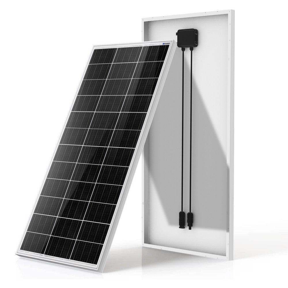
ECO-WORTHY SOLAR PANEL​

195 Watt 12V Solar Panel​

  • Rated power: 195W
  • Open-Circuit Voltage (Voc): 22.8V
  • Short circuit current (Isc): 12.23A
  • Working current (Iop): 10.27A
  • Output Tolerance: ±3%
  • Size: 58.3x26.3x1.4inches
  • weight: 28.2 Lbs
  • Power: 5 year/95% efficiency rate
  • 10 year/90% efficiency rate
  • 25-year/80% efficiency rate
2 AWG connector length from battery to inverter is 3' +/-
Solar cable with MC4 connectors from farthest PV panel to charge controller will be 20'-25'.

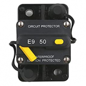
Circuit breaker between positive invertor/battery and EPEVER 40A charge controller:​

E9 50 Amp Circuit Breaker with Switch Manual Reset​

Interrupt Capacity:
  • 2,500A @ 14Vdc (25-200A)
  • 1,500A @ 48Vdc (25-200A)
  • 1,500A @ 14Vdc (225A-300A)
  • Voltage: up to 48Vdc
  • Current Rating: 25-150A @ 72V dc; 200A-300A @ 48V dc
  • Mounting Wide: Surface Mount
  • Reset Type:T3, Manual reset (25-200A @ Switchable)
  • Operating Temperature: -32ºC (-25ºF) to 82ºC (180ºF)
  • Regulatory Specification: SAE J1625; SAE J1171; UL 1500; ABYC E-11; CE; IP67
  • Termination: 1/4" Stainless Steel Studs
  • Body: UL-rated 94V0 thermoset plastic
  • Storage Temperature:-34ºC (-30ºF) to 149ºC (300ºF)
  • Compliances: J553, J1625, J1171, UL 1500 (Ignition protected)
 
Last edited:
"Short circuit current (Isc): 12.23A"

2 x 12.23 x 1.56 = 38A
An 8 awg "Y" cable would work, except don't trust MC4 on output. Or two, 12 awg or larger pigtails joined in a box to 8 awg (or separate runs back to charge controller)

50A breaker AIC isn't high enough for battery's 4000A capability, so should connect to the (150A?) fuse that also feeds inverter.

3' is short enough 2 awg is OK. Just give them access to air for cooling.

What is the MPPT voltage range of your charge controller? Need to make sure Vmp from panels is high enough even on a hot day. What is temperature coefficient of Vmp for panels?

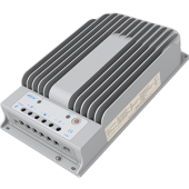
Tracer 4215BN MPPT 40A

Max PV Input Volt: 150V/138V(At 25℃ temperature)
Grounding: Negative Ground
Rated Input Power: 520W@12V / 1040W@24V
Max Input Power: 1560W@12V/3120W@24V(12V or 24V refers to battery voltage)

Hedges, while I do very much appreciate your time and knowledge, you lost me awhile back. You knowledge and attention to detail are overwhelming. I have zero...no experience whatsoever with electricity or solar/pv projects at all.
All the abbreviations and electrical specs are Greek to me. Please excuse my ignorance.

I guess I was just hoping for a list of items or simple suggestions that I could source and assemble.
I have the charge controller, the inverter. PV panels and mounting hardware are purchased and being shipped as we speak. I have 2 AWG connectors for the battery/inverter connection and solar panel disconnect. Batteries have not been purchased. Was hoping to assemble system myself. Project may be more involved than I anticipated.
No offence intended.
RJ
 
Last edited:

"MPP Voltage range Vbat + 2V to 108V"
That's good, PV panels only need to be 2V higher than battery to work.

AGM batteries probably want up to 14.5V per 12V, so 29V for 24V battery. Charge controller 2V higher, need 31V from PV, even on a hot day.

Have a link to the PV panel specs? Possibly two panels in series won't be high enough voltage, but three would (3s). I'll check the specs to see of two work (for 2s2p)

I have difficulty with most Greek characters too. Those kept showing up in engineering and math classes. "Ω" is the only one I'm comfortable with.
I don't have spec/data sheet for the panels.

Was hoping to just buy needed components off the shelf then plug and play. Was not anticipating all the variables.

A 4th panel can be purchased if needed to charge correctly.

Thanks for understanding.

RJ
 
I don't have spec/data sheet for the panels.

Was hoping to just buy needed components off the shelf then plug and play. Was not anticipating all the variables.

A 4th panel can be purchased if needed to charge correctly.

Thanks for understanding.

RJ


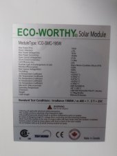
It is a 36 cell panel.
For some reason, they don't list voltage for peak power.

OK, 195W / 10.27A = 19.0V
2 x 19V = 38V
That should work fine with 2 in series for the charge controller. Even on a hot day, voltage would not drop 18% to the 31V minimum.

"Open-Circuit Voltage (Voc): 22.8V"

"Max. PV open circuit voltage 150V (at minimum operating environment temperature) 138V (at 25℃ environment temperature)"

It could tolerate up to 5 of these panels on a very cold day according to voltage limit, possibly 6 panels if your location doesn't get too cold.

It is OK wired 2s, 3s, 4s, 5s, 2p2s, 2p3s. So you can use 2 to 6 panels and have all their power used. There are ways to make use of more panels if desired.
 
Thanks Hedges and everyone else!

Looking for appropriate DC interrupt switch between 24V battery bank and system...suggestions on
brand and model would be great.
20210614_103332[3111].jpg
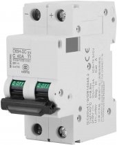
Also, will the following circuit breaker be sufficient between the 3s-195W panels (possibly a 4th panel added later) and the 40A charge controller? 2P C65H-DC 250V 25A/40A Low-Voltage DC Miniature Circuit Breaker

20210616_142517.jpg61+IQ9U3pzL._AC_SL1500_.jpg3b08ff48-230f-4bd8-98eb-b818846f04a8._CR0,0,300,300_PT0_SX300__.png

If not, maybe a suggestion with appropriate model and brand also.

You've all been a great help...thanks again! RJ
 
Thanks Hedges and everyone else!

Looking for appropriate DC interrupt switch between 24V battery bank and system...suggestions on
brand and model would be great.
View attachment 53329

Can't tell what brand 50A circuit breaker in that picture. There are good ones and bad ones. Only the good ones will carry charge current without tripping and also open if battery dumps current into a short.

Here are some switches. If you want to use a lithium battery, a 2-position switch can be used with a precharge resistor.


Also, will the following circuit breaker be sufficient between the 3s-195W panels (possibly a 4th panel added later) and the 40A charge controller? 2P C65H-DC 250V 25A/40A Low-Voltage DC Miniature Circuit Breaker

View attachment 53330View attachment 53331View attachment 53332

If not, maybe a suggestion with appropriate model and brand also.

You've all been a great help...thanks again! RJ

"25A/40A"? I don't see 25A.

"Short circuit current (Isc): 11.89A"

11.89A x 2 string in parallel x 1.56 = 37A, 40A breaker should be good for 3s2p, 4s, etc.
(I meant to type 2s2p, 3s2p in earlier post. 2p2s might be done for batteries, not PV panels.)
 
Thanks Hedges. Here is the circuit breaker brand you could not see in earlier picture...T Tocas 50 A Circuit Breaker...1624255028257.png
 
Thanks Hedges. Here is the circuit breaker brand you could not see in earlier picture...T Tocas 50 A Circuit Breaker...View attachment 53545

Here are some we would trust:


You pays your money and you takes your chances.


(Although, some reviewers don't understand trip curves and the time it takes wire to heat up:

"Take a look at the chart that's included with the breaker. In my case, I have a 50 Amp breaker. According to the chart, if 75 Amps (50% more than rating) are flowing, it can take between 30 seconds and 150 seconds for the breaker to trip (the hashed area in the chart). If current flow is just 20% over the rating (60 Amps), it could take between 150 seconds and "never" to trip."

That matches how some breaker types from name brands are documented to perform, and I've spot-checked at a couple of current levels.)


Thanks for being so helpful Hedges!

Any thoughts on 4-stud bus bars/4-stud distribution blocks for positive and negative? Amp rating?

RJ
 
Any thoughts on 4-stud bus bars/4-stud distribution blocks for positive and negative? Amp rating?

Size it for maximum continuous inverter draw. Compute that from output wattage rating, lowest battery voltage, inverter efficiency at 100% (not peak efficiency), add 25% margin.

Many vendors or make your own. Cross section of metal is more certain than what's inside a breaker.
 
Thanks again Hedges, MisterSandals and everyone else.

Grounding panels...I understand that PV panels should be grounded to their own rod. Does rod need to be a full 8' or can it be shorter? I'm seeing them online in 4' 6' and 8' lengths.

Also, my system will be mobile. How would one ground the components (inverter, charge controller, cart) on an audio/visual cart?
Please excuse my ignorance and thanks again for your time and expertise.
RJ
 
Not so sure their own grounding rod is required. (If in a lightning-prone area, a lightning rod with its own ground rod might be used.)
PV panel frames should be tied back to chassis ground of the electrical equipment. (Not needed if PV voltages are low enough to be touch-safe)

Portable systems are a bit of an issue. Ideally grounded to something, and with GFCI outlets. If used indoors you can use an extension cord to connect to ground of wall outlets.
Hedges...after re-reading your post, do I understand that the panels should be grounded to the houses electrical system?
 
The PV panel frames should be grounded to the charge controller or inverter, so if PV+ or PV- wires short to frame, there is a path back to equipment chassis.

The system produces AC which can be a shock hazard. Plugging an extension cord into house electrical would be a way to ground it.
Some systems will work as a UPS, pass through grid when up and transfer to batteries when it isn't.
All depends on your application.

Inverters for mobile and boat applications usually have a relay to bond AC neutral wire to ground when unplugged from grid, but disconnect that internally when plugged into "shore power" which provides the ground bond.

Portable inverters are a bit of a conundrum. They generate hazardous voltages but usually have no ground rod available. What you do with them depends on application, what minimizes risk. If used outdoors, GFCI would be a good idea.
So, if I plug an extension cord into wall, what is done with other end; female end?
 
You could have a power cord with hot and neutral capped, just connect ground to chassis.

I sometimes do similar for lab work, with an alligator clip attached to the green ground wire. That provides a ground for equipment on the bench.

That takes care of keeping the metal surfaces at ground potential. It can also go to ground of any receptacles.
Depending on whether the inverter tolerates it, you might also tie neutral of inverter go ground (some cheap lightweight models aren't compatible with that). Or, you might have an inverter which does that automatically when it doesn't detect shore power.
 
Back
Top