diy solar

diy solar

What BMS is needed forThis.

hpwells1

New Member
Joined
Feb 13, 2023
Messages
18
Location
Minnesota
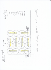
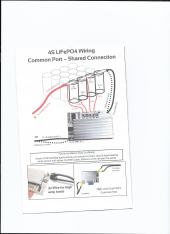
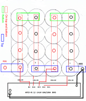
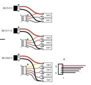
Hello all. I am building or should I say rebuilding a 12volt battery using 16 headway 38120 cells. I previously was only using 8 of these cells and I was using a APEX 4s12V-14.6V 60A/100A BMS connected in the Common Port-Shared Connection. It didn't seem to last as long as I thought it should. So my question is: "What BMS should I be using for 16 cells???. This is only a 12Volt battery and all the s 16 BMS are for 48 volts.Please see attached picture and pleas help if you can.

Thank You

hpwells1
 

Attachments

  • Scan_20230213.png
    Scan_20230213.png
    638.3 KB · Views: 12
Ok, so the bms I have now will work? and could you explain to me where on my picture the #1,2,3 and 4 wires (on the bms) would connect to?.
ie, positive 1,2,3,4. If so I don't see how it could measure the voltage for the remaining 12 cells. I guess I just don't understand. I thought you needed a wire for each cell.
 
A 4S BMS will work but not the way you have them jumpered, in your diagram 9-16 aren't in the circuit. What you need to do is connect 3 cells together, pluses and minuses jumpered together. Make 4 groups of 3 cells like that and put the 4 groups in series. Your BMS wires will go to each group of 3 cells and will monitor them as a group.
 
You have depicted 2X 2P4S batteries. You need 2X 4S BMS and a reconfigure of the terminals.

Cells in parallel are effectively one cell, so they can't be monitored individually.


1676329818814.png
 
so with this diagram would the 4 connections on the BMS (B+, B2, B3, & B4 go to Cells positive 1,2,3 & 4?? and will each connection balance that roll of cells???.

hpwells1
 
so with this diagram would the 4 connections on the BMS (B+, B2, B3, & B4 go to Cells positive 1,2,3 & 4?? and will each connection balance that roll of cells???.

hpwells1
The top row (negative end of the battery) is cell 1.
Pin 1 goes to top of row 1.
Pin 2 goes to bottom of row 1.
Pin 3 goes to top of row 2.
Pin 4 goes to bottom of row 3.
Pin 5 goes to top of row 4. (positive end of battery).

The connections will not balance the cells within rows.

With 4P, it will help if each row total capacity is equal to each other row. So do not put all the strongest cells nor all the weakest cells together within a 4P row.
 
I take it that this is a 4p battery
4P4S battery (4S battery but each "logical cell" is really 4 physical cells in parallel, acting as one with combined capacity).

If i were to label the cells as drawn:
A B C D -
E F G H
I J K L
M N O P+

A, B, C, D combine in parallel to form "cell 1" in the 4S scheme (negative end of the 4S battery)
E, F, G, H combine in parallel to form "cell 2"
I, J, K, L combine in parallel to form "cell 3"
M, N, O, P combine in parallel to from "cell 4" (positive end of the 4S battery)

4P4S
 
The connections will not balance the cells within rows.
In a parallel 4P4S configuration all the cells will get balanced, just not individually. The parallel cell groups will get balanced as a group because the physics of parallel connections will make sure the parallel cells are all a the same voltage.
 
Thank you again for the info. I am hooking up my balance connector, however my connectors have one red wire and 4 black. I know the red wire goes to the positive (cell #4) but how are the other black wires connected (pos. or neg to cells 1,2,3)?? Please see attached photos.
 

Attachments

  • 1676330385415.png
    1676330385415.png
    821.4 KB · Views: 5
  • lipo-balance-plug.jpg
    lipo-balance-plug.jpg
    39.5 KB · Views: 5
I know the red wire goes to the positive (cell #4) but how are the other black wires connected (pos. or neg to cells 1,2,3)
Its easier to describe starting from the black wired end of the connector.
The end black wire goes to negative of cell 1 (negative end of battery). This 1 call pin 1.

Pin 2 (its unfortunate use of black wire) goes to positive of cell 1.
Pin 3 to positive cell 2.
Pin 4 to positive of cell 3.
Pin 5 to positive of cell 4.

Checking your work BEFORE connecting, measure voltage between pin 1 and pin 2. Should be ~3.2V.
Between pin 1 and pin 3 should be ~6.4V
Between pin 1 and pin 4 should be ~9.6V
Between pin 1 and pin 5 should be ~12.8V (whole battery voltage)
 
how are the other black wires connected (pos. or neg to cells 1,2,3)??
@MisterSandals beat me to it.
Each black wire is attached to the busbar for 1,2,3&4. Since this is also the positive of the next cell it is similar to a BMS with one black wire and four red wires except in this case it starts from the Positive pack terminal and works down.
 
Thanks guys. now for another problem. I connected my BMS along with my battery charger and at the end of charge I have two red lights on my BMS. B-2 and 3 without the charger connected. Is this common??
 
Last edited:
Those are balance status lights. What are the voltages of your cells?
Any idea what the balance parameters and hysteresis of charging is?

Wondering if 2 lights on means 2 being charged (active balancing) or discharged (passive balancing)?
 
What are the voltages of your cells? They run from 3.31 to 3.33volts.

Any idea what the balance parameters and hysteresis of charging is? No idea what so ever.
I did edit my previous thread as to say the lights were on without my charger attached and now I see only one red light.
 
Back
Top