diy solar

diy solar

What I'm learning about DIY Enphase and Hoymiles Microinverters

Update: Actually, it is easy to see the DC side of the Hoymiles. Panel current was 0.00 all night. The only losses are on the grid side.
I think you lost focus there...
  • the first video claimed there was a lot of reactive power consumed at night when the rooftop microinverters weren't generating power.
  • That video (now deleted) was replaced by a better one saying sure there's current that can be measured there because of the capacitors. But, that energy isn't consumed so it's not a problem on-grid. But off-grid, the energy has to be supplied by the inverter which is a problem because of inverter losses.
  • I'm not so sure, it depends on which side of the inverter the energy is conserved at. To answer that, I think you'd need to measure the DC side from the battery feeding the inverter (not the roof-top inverter ; -).

... I think you may have some idea that CTs can't be trusted. ...
I've no problem with CTs, I just didn't want you thinking it was actually measuring watts (e.g., the statement "it's not a VA meter"). It really is a VA meter, just has some brains to convert what it does measure into different ways to understand the readings. It's a fine distinction, but a lot of bad experimental results come from not understanding what you're really measuring. Apologies if I'm being overly pedantic; I drive a lot of people crazy unintentionally.
 
No worries, I just hooked up the HM inverter to an adjustable DC power supply, powered by a DC-AC AIMS 650VA inverter/charger, supplied by a 12V, 50Ah, PowerQueen battery. I need a long extension cord to charge it, but I want to see if it works. Waiting, 3 minutes to go...
 
No worries, I just hooked up the HM inverter to an adjustable DC power supply, powered by a DC-AC AIMS 650VA inverter/charger, supplied by a 12V, 50Ah, PowerQueen battery. I need a long extension cord to charge it, but I want to see if it works. Waiting, 3 minutes to go...
Here is the test data. It works like a charm! Anyone want an AC coupled battery for energy storage and export usage at night?

Microinverters as Grid-Tied AC Battery (No ads)

36-51V LiFePO4 batteries can be connected directly to the microinverter with a 15A fuse. You can charge the battery DC coupled with a charge controller, such as the AIMS 40A, or you can use an AC charger to charge the battery from the grid.

When I get the meter next week, I will test it again and verify the zero-export function, then it's ready to be paired with an off-grid system. Nice! Easy! Cheap! I love it!
 
Last edited:
Here is the test data. It works like a charm! Anyone want an AC coupled battery for energy storage and export usage at night?

Microinverters as Grid-Tied AC Battery (No ads)

36-51V LiFePO4 batteries can be connected directly to the microinverter with a 15A fuse. You can charge the battery DC coupled with a charge controller, such as the AIMS 40A, or you can use an AC charger to charge the battery from the grid.

When I get the meter next week, I will test it again and verify the zero-export function, then it's ready to be paired with an off-grid system. Nice! Easy! Cheap! I love it!
Can/dare I make a suggestion?
From my understanding so far (and I could be dead wrong) California Rule21 grid selection would imo make the HM micro inverters "more sensitive" to freq shifting. Whatever test you did, what if you "just for fun" change your HM grid settings to US-CA rule21 and see if they modulate more/better?
Why not? I think that's easy to do, but the inverter is offline right now. Great idea. Thanks!
 
From my understanding so far (and I could be dead wrong) California Rule21 grid selection would imo make the HM micro inverters "more sensitive" to freq shifting.
Yes, that is a good suggestion. My understanding is CA Rule 21 and UL1741SA are the same and I just assumed that it was the spec he was working with but it is alway useful to check assumptions. My only other suggestion that would help understand what is going on would be some measurement of freguency during these tests. Of course that would have to be when in microgrid mode because the 60 Hz of the grid is not going to reveal anything because the grid also presents infinite load and there would be no reason for the IQ8 System Controller 2 to change the frequency when the grid is active.
 
My only other suggestion that would help understand what is going on would be some measurement of freguency during these tests. Of course that would have to be when in microgrid mode because the 60 Hz of the grid is not going to reveal anything because the grid also presents infinite load and there would be no reason for the IQ8 System Controller 2 to change the frequency when the grid is active.
From what I could I see on the video the frequency was one of the things that was made visible on graph on the HM brains. Am I correct ncsolarelectric?
 
From what I could I see on the video the frequency was one of the things that was made visible on graph on the HM brains. Am I correct ncsolarelectric?
Yes, but it's 1 data point every 15 minutes. Difficult to tell how it's changing. The lowest I saw was 59.8Hz, and the highest was 60.3Hz.
 
Why not? I think that's easy to do, but the inverter is offline right now. Great idea. Thanks!
Found out, that is what it is set for already. Here are the grid profile parameters currently set. Power starts limiting at 60.1 Hz. Enphase must be more sensitive than that, maybe?
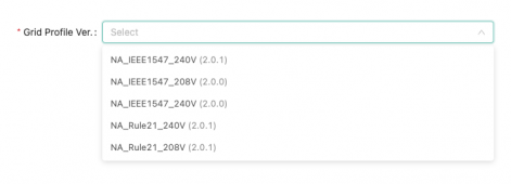
These are the options as well.

Screen Shot 2022-08-01 at 7.05.44 AM.png

Grid Profile
NameValueUnit
NA_Rule21_240V-
CountryStd512-
Version8193-
H/LVRT-
H/LVRT F&C Code53
Nominal Voltage (NV)240V
Low Voltage 1 (LV1)211.2V
LV1 Maximum Trip Time (MTT)21s
High Voltage 1 (HV1)264V
HV1 Maximum Trip Time (MTT)13s
Low Voltage 2 (LV2)168V
LV2 Maximum Trip Time (MTT)11s
High Voltage 2 (HV2)288V
HV2 Maximum Trip Time (MTT)0.16s
Low Voltage 3 (LV3)120V
LV3 Maximum Trip Time (MTT)1.5s
Momentary Cessition Low Voltage120V
Momentary Cessition High Voltage264V
H/LFRT-
H/LFRT F&C Code4099
Nominal Frequency60Hz
Low Frequency 1 (LF1)58.5Hz
LF1 Maximum Trip Time (MTT)300s
High Frequency 1 (HF1)60.5Hz
HF1 Maximum Trip time (MTT)300s
Low Frequency 2 (LF2)57Hz
LF2 Maximum Trip Time (MTT)0.16s
High Frequency 2 (HF2)62
HF2 Maximum Trip Time (MTT)0.16s
Islanding Detection (ID)-
ID F&C Code8192
ID Function Activated1
Reconnection (RT)-
RT F&C Code12291
Reconnect Time (RT)300s
Reconnect High Voltage (RHV)264V
Reconnect Low Voltage (RLV)211.2V
Reconnect High Frequency (RHF)60.5s
Reconnect Low Frequency (RLF)58.5s
Ramp Rates(RR)-
RR F&C Code16384
Normal Ramp up Rate (RUR_NM)100Rated%/s
Soft Start Ramp up Rate (RUR_SS)2Rated%/s
Frequency Watt (FW)-
FW F&C Code20497
FW Function Activated1
Start of Frequency Watt Droop (Fstart)60.1Hz
FW Droop Slope (Kpower_Freq)50Pn%/Hz
Recovery Ramp Rate (RRR)2Rated%/s
FW Settling Time (Tr)5s
Volt Watt (VW)-
VW F&C Code24576
VW Function Activated1
Start of Voltage Watt Droop (Vstart)254.4V
End of Voltage Watt Droop (Vend)259.2V
VW Droop Slope (Kpower_Volt)20.83Pn%/V
Volt Var (VV)-
VV F&C Code32769
VV Function Activated1
Voltage Set Point V1220.8V
Reactive Set Point Q130%Pn
Voltage Set Point V2232.1V
Voltage Set Point V3247.9V
Voltage Set Point V4256.8V
Reactive Set Point Q430%Pn
VV Setting Time (Tr)5s
Specified Power Factor (SPF)-
SPF F&C Code36864
SPF Function Activated0
Power Factor (PF)0.95-
Active Power Control (APC)-
APC F&C Code28672
APC Function Activated1
Reactive Power Control (RPC)-
RPC F&C Code40962
RPC Function Activated0
Reactive Power (VAR)0-
 
Here is the test data. It works like a charm!
Nice to have that confirmed! Nice to also see that even as cloudy as it was it was still outputting 187W (5:18) (although, that's probably more about the panel ; -).

I suspect part of what you were seeing with the Drok voltage may have been the HM's MPPT interacting with it. Impressive the Drok didn't sag when the HM became active.
 
@fromport How does the Encharge handle having a generator run in parallel through the generator port on the SC2? How does the SC2 prevent the generator from back-feeding the battery? It doesn't have P/f control.
 
Nice to have that confirmed! Nice to also see that even as cloudy as it was it was still outputting 187W (5:18) (although, that's probably more about the panel ; -).

I suspect part of what you were seeing with the Drok voltage may have been the HM's MPPT interacting with it. Impressive the Drok didn't sag when the HM became active.
It's a really crapy scratchy potentiometer and I had too much coffee. However, when the voltage was low and the PS was running in constant current mode, it did exhibit that behavior. After I set it, the voltage would drop and the current was maxed out. To control the output of the microinverter requires a power source operating with current-mode control like a buck converter, not voltage control. I don't see too many OTS power supplies that have a controllable interface, like the old GPIB units. What do they use these days for test equipment anyway?
 
@fromport How does the Encharge handle having a generator run in parallel through the generator port on the SC2? How does the SC2 prevent the generator from back-feeding the battery? It doesn't have P/f control.
a)
I have no experience yet with hooking up a generator to an enphase system controller 2.
When it was discussed during the hands on training day it was referred to as "possible but with a lot of exceptions"
Older generators are likely not to work together, so people would be forced to replace their genset as well.

b)
I just looked up some documentation.
There is a list of approved generators.

c)
This document https://enphase.com/sites/default/files/2021-10/Enphase-Generator-Support-Technical-Brief.pdf
literally says "Back feed protection for remote start generator with M-series" and advises to install a shedding relay.

I don't have any feedback from real life experience.
 
Oh, this is absolute gold! Thank you.

Screen Shot 2022-08-01 at 9.50.38 AM.png

This makes it incredibly easy to connect an AC-coupled HM + Battery ESS to my existing Enphase system. It never needs to run when the Encharge is fully charged, so it can't back feed the battery inverters, they will simply use the energy to re-charge from the HM battery. So I could pair an 48V, LG Chem, EG4, or other UL Listed 48Vdc battery, with a bunch of HM microinverters and extend my Enphase battery capacity "cheap". Awesome!

@Ampster did you notice the parameters you were looking for in that grid profile regarding P/f droop, and P/V droop? Both of those specs are in there. As I suspected, it works in the positive direction for voltage. If the voltage exceeds 254.4Vac, the power drops 20.83%/V, so at 259.2Vac the power has dropped to zero.
Apparently, the FW is also one-sided. It starts at 60.1Hz and power is reduced at 50%/Hz at a rate of 2%/s. At 62Hz, the power is reduced to zero, but what about 58Hz? It's not on there.

Frequency Watt (FW)-
FW F&C Code20497
FW Function Activated1
Start of Frequency Watt Droop (Fstart)60.1Hz
FW Droop Slope (Kpower_Freq)50Pn%/Hz
Recovery Ramp Rate (RRR)2Rated%/s
FW Settling Time (Tr)5s
Volt Watt (VW)-
VW F&C Code24576
VW Function Activated1
Start of Voltage Watt Droop (Vstart)254.4V
End of Voltage Watt Droop (Vend)259.2V
VW Droop Slope (Kpower_Volt)20.83Pn%/V
 
What do they use these days for test equipment anyway?
The manual ones can be had fairly cheaply, but those with APIs are expensive... that's why I came up with the PWM approach. After seeing your setup though I've realized you don't even need the PWM. Just like the chargers are stacked in that drawing to accomodoate different levels of solar power, the microinverters can also be stacked for incremental power output. I'll put up an alternate drawing when I get some time.

How does the SC2 prevent the generator from back-feeding the battery? It doesn't have P/f control.
The Enpower has a relay switch it uses to turn the generator on/off, the Envoy decides when and it's configurable and the output is voltage controlled (generators are a voltage source after all).

As to back-feeding, it's not 100% prevented; that's why the Enphase engineering documents requires the minimum generator size be roughly on par with the number of active panels (that is you can also use PV shedding when the generator is running if needed).
 
Last edited:
...It never needs to run when the Encharge is fully charged, so it can't back feed the battery inverters...
Enphase engineering covers the daylight_solar+battery+generator use case; but... if you only run at night then solar surge must always be zero.


Apparently, the FW is also one-sided. It starts at 60.1Hz and power is reduced at 50%/Hz at a rate of 2%/s. At 62Hz, the power is reduced to zero, but what about 58Hz? It's not on there.
Frequency-watt power throttling is only greater than 60 Hz for the U.S. grid. However, under 60 Hz will soon be a methodology by which a utility can request more power from ESSes (e.g., a home-owner with a grid-tied battery).
 
Frequency-watt power throttling is only greater than 60 Hz for the U.S. grid. However, under 60 Hz will soon be a methodology by which a utility can request more power from ESSes (e.g., a home-owner with a grid-tied battery).
Nice!
I can see how being able to write and install my own grid profile would be incredibly powerful.
 
This makes it incredibly easy to connect an AC-coupled HM + Battery ESS to my existing Enphase system. It never needs to run when the Encharge is fully charged, so it can't back feed the battery inverters, they will simply use the energy to re-charge from the HM battery. So I could pair an 48V, LG Chem, EG4, or other UL Listed 48Vdc battery, with a bunch of HM microinverters and extend my Enphase battery capacity "cheap". Awesome!
Are you saying that the Enphase System Controller 2 has 48 volt leads so you can add battery capacity to the Encharge? If so wouldn't that allow DIYers to cannibalize sales of Encharge batteries?
@Ampster did you notice the parameters you were looking for in that grid profile regarding P/f droop, and P/V droop? Both of those specs are in there. As I suspected, it works in the positive direction for voltage. If the voltage exceeds 254.4Vac, the power drops 20.83%/V, so at 259.2Vac the power has dropped to zero
Thanks. I understand the general concept of UL1741SA and how it works. I am not well versed in the terms p/f and P/V droop but so far have not found a need to think about those things. The unanswered question for me in your earlier experiment is whether the System Controller 2 is using frequency or voltage to control the AC coupled inverters.
 
Are you saying that the Enphase System Controller 2 has 48 volt leads so you can add battery capacity to the Encharge? If so wouldn't that allow DIYers to cannibalize sales of Encharge batteries?
No, I'm saying that it can control turning a generator on/off based on the SOC of the Encharge battery. The generator, in this case, is the HM microinverters pulling power from a 48Vdc battery bank.

Thanks. I understand the general concept of UL1741SA and how it works. I am not well versed in the terms p/f and P/V droop but so far have not found a need to think about those things. The unanswered question for me in your earlier experiment is whether the System Controller 2 is using frequency or voltage to control the AC coupled inverters.
Unfortunately, I don't have a means of observing frequency and power simultaneously in real-time (yet). Just one sample every 15 minutes or so. The weather is not cooperating either. Clouds coast to coast. I can look for Power/Voltage control, but I never saw the microgrid go above 241V. According to the grid parameter, it would need to be above 254.4Vac, and I can confirm that didn't happen.
 
a)
I have no experience yet with hooking up a generator to an enphase system controller 2.
When it was discussed during the hands on training day it was referred to as "possible but with a lot of exceptions"
Older generators are likely not to work together, so people would be forced to replace their genset as well.

b)
I just looked up some documentation.
There is a list of approved generators.

c)
This document https://enphase.com/sites/default/files/2021-10/Enphase-Generator-Support-Technical-Brief.pdf
literally says "Back feed protection for remote start generator with M-series" and advises to install a shedding relay.

I don't have any feedback from real life experience.
Ah! There's the rub. If the generator isn't on the list, it isn't in the Installer App, so the generator port of the SC2 can't be activated. So it's a no-go doing it that way unless I buy one of those generators to activate it. :mad:
 
...If the generator isn't on the list, it isn't in the Installer App, so the generator port of the SC2 can't be activated...
Given there are only two wires representing on/off, I suspect you could pick anything on the list and it would at least appear to work.
The question is what's under the covers in terms of timing/power limits. Although once activated, those might be adjustable.
 
Are you saying that the Enphase System Controller 2 has 48 volt leads so you can add battery capacity to the Encharge? If so wouldn't that allow DIYers to cannibalize sales of Encharge batteries?

Thanks. I understand the general concept of UL1741SA and how it works. I am not well versed in the terms p/f and P/V droop but so far have not found a need to think about those things. The unanswered question for me in your earlier experiment is whether the System Controller 2 is using frequency or voltage to control the AC coupled inverters.
It looks like Enphase did use P/f control to curtail the HM inverter. See my latest experiment with lots of data.

(Wonder why my dog is named Data?)
 

diy solar

diy solar
Back
Top