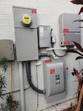
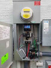
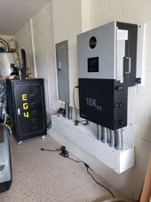
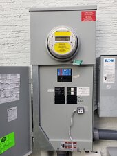
I bought a EG4 18Kpv and 30kWh of LifePower4 batteries to add to an existing 8kW solar array and grid-tied inverter. The existing grid-tied system can feedback 32A max through a 40A feedback breaker. This stays within the 120% rule for the 200A busbars in that breaker panel. My preference is to only use the batteries as backup, for grid down emergencies, and not use them for grid feedback or to power loads when the grid is available.
I will be AC-coupling the existing solar system through the GEN terminals, so I need to calculate the total max feedback to the grid from the EG4 inverter. I will not be adding any additional PV to the EG4's DC input terminals at this time. Will the 32A from the AC-coupled system still be available for feedback to the grid?
I understand that the maximum continuous output from the EG4 18Kpv is 12000W/50A, so if I were to add 12000W or more of solar panels to the MPPT connections in the future, that 50A could be fed back to the grid. True? Assuming that I had 12000W of additional solar panels attached, would the EG4 inverter add its max output (50A) to the AC-coupled input (32A) to afford 82A of solar feedback to the grid? The Signature Solar techie told me that the EG4 18Kpv would limit the feedback to a maximum of 50A, although she seemed a little iffy about it. That doesn't seem logical to me since the AC-coupled input doesn't put any load on the new inverter.
Without adding additional solar, the batteries could easily max out the EG4 18Kpv's AC output. Can any battery power ever get fed back to the grid? I didn't notice anything in the manual that suggests that it could. Signature Solar says that battery power will never be fed back to the grid.
I want to avoid having to de-rate my main breaker for the 120% rule. If I only have to do my calculations with the AC-coupled 32A, then I stay with the 40A feedback breaker and my 200A main breaker. If I have to add potential 50A feedback from the batteries, or 50A from potential future solar panel additions, to the 32A from AC-coupling, I will have to de-rate my main breaker to 125A. I noticed a setting for limiting the AC feedback to the grid in the manual. Will using this setting to limit my feedback be acceptable to local inspectors, or will they always require me to use the theoretical max output from the EG4 inverter (for my physical configuration) to determine the 120% rule?
I am assuming, for now, that I only have to use the 32A AC-coupling input as my max grid feedback current for this installation. I will be doing my permit application in several days, and would appreciate any feedback you might have on these questions.
If anyone is going to suggest using feeder taps, I met today with the local inspectors to discuss how I could take that approach, and it appears to be more complicated than I want to take on at this time. My existing utility hookup does not lend itself to feeder taps without major modifications and new electrical boxes.