The contactor specs show this as a normally open contactor with relay coil resistance of 3.14 ohms. If the battery voltage is 13.8v for example, wouldn't this be drawing about 4.4 amps continuously to keep the contactor closed during normal battery charging/usage?
You are using an out of date browser. It may not display this or other websites correctly.
You should upgrade or use an alternative browser.
You should upgrade or use an alternative browser.
Why not to use Daly BMS with MPPT controllers
- Thread starter Blue-Flower
- Start date
I did find DC-DC buck converters on eBay @ 2 for ~ $1.00 and plan to build the initial circuit with one of those, rather than a zener supply. I don't intend to have battery supply voltage drop below 12v, but will test it down to 10v.The important bit is the schmitt trigger, the buck converter is just a power supply and could easily be replaced by a zener/resitor arrangement, the actual power consumption is minimal (a few mA when the relay is on).
@Davismltc did a version for a 12V pack with a zener supply.
Input 3.2v~40v
Output 1.25~30v
Current 3A (max)
Last edited:
BradCagle
Solar Enthusiast
- Joined
- Aug 27, 2021
- Messages
- 578
The contactor specs show this as a normally open contactor with relay coil resistance of 3.14 ohms. If the battery voltage is 13.8v for example, wouldn't this be drawing about 4.4 amps continuously to keep the contactor closed during normal battery charging/usage?
No. This particular contactor has Tyco's "Economizer" that lowers the holding current after it closes. It's I assume a chopper circuit like you would see on stepper motor controllers.
I've measured it, and it only requires 1.7w to hold.
■ Built-in coil economizer – only 1.7W hold power @ 12VDC and it limits back EMF to 0V. Models requiring extenal economizer also available
Hedges
I See Electromagnetic Fields!
- Joined
- Mar 28, 2020
- Messages
- 21,607
The contactor specs show this as a normally open contactor with relay coil resistance of 3.14 ohms. If the battery voltage is 13.8v for example, wouldn't this be drawing about 4.4 amps continuously to keep the contactor closed during normal battery charging/usage?
No. This particular contactor has Tyco's "Economizer" that lowers the holding current after it closes. It's I assume a chopper circuit like you would see on stepper motor controllers.
I've measured it, and it only requires 1.7w to hold.
That's one possibility. Then you get all the reliability of a semiconductor driver, for a device as simple as a coil of wire and Gauss's law for magnetism. Sometimes, silicon is the most reliable part of a product, and sometimes it is the first to go.
A PTC thermistor could also serve as an economizer, but would dissipate much more energy in its resistance than is needed for IR drop of the coil to generate sufficient magnetic field.
Can you measure AC signal coming from your economizer as it switches?
I prefer the economizer in a contactor resold by SMA (made by ABB, if I recall correctly.)
It has two windings on the core. One has 10 ohms DC resistance, which would draw 5A, 250W from 50V battery if left connected. That slams the contacts closed hard. A small NC auxiliary contact shorts out a high resistance winding in series with the 10 ohm winding. As soon as relay coil has pulled in the core and closed contacts, this inserts a high resistance, high turn count winding in series. The 50V battery voltage is dropped across the long, thin wire of second winding, producing enough field strength to hold relay closed.
Here's a similar scheme, dual parallel coils from Gigavac. Uses electronic timer rather than separate electromechanical contact.
BradCagle
Solar Enthusiast
- Joined
- Aug 27, 2021
- Messages
- 578
I think just a little over 2wThat's awesome! I only saw the specs on battery hookup.
What's the power draw for the combined units together (e.g. the controller relay and contactor together)?
BradCagle
Solar Enthusiast
- Joined
- Aug 27, 2021
- Messages
- 578
Can you measure AC signal coming from your economizer as it switches?
I don't have a scope ATM.
Here's a link to the guts of the economizer http://myelifenow.blogspot.com/2013/03/opening-up-tyco-kilovac-ev200aaana.html
Last edited:
You can also have a capacitor in // with a resistor and the whole thing in series with the relay coil. The capacitor allow a burst of high current at first and then it become open circuit so the current gets limited by the resistor. It's not the most efficient solution but it avoids semiconductors and should last at least as long as the rest of the relay.
BradCagle
Solar Enthusiast
- Joined
- Aug 27, 2021
- Messages
- 578
You can also have a capacitor in // with a resistor and the whole thing in series with the relay coil. The capacitor allow a burst of high current at first and then it become open circuit so the current gets limited by the resistor. It's not the most efficient solution but it avoids semiconductors and should last at least as long as the rest of the relay.
Interesting. The cap will pass current until its fully charged, then it blocks the dc. But won't the resistor just burn up/waste the current it's limiting to the contactor?
Yep, exactly. You need to take into account the power dissipated in the resistor.
It start to get a problem with bigger relays as the coil will have a higher power consumption.
But just for an example for a relay coil rated 24 V and 50 Ohms, the nominal current would be 0.48 A. Let's say we can reduce the current to 1/3 of the nominal once the relay toggled (1/3 to 1/2 is a safe bet for any relay usually) so 0.16 A. At 24 V that would be a 150 Ohms load so the resistor would need to be 100 Ohms. Then the power dissipated in the resistor would be 2.6 W so a 5 W resistor would be ok, a 10 W one or more would be better.
The Kilovac must be specifically designed to be able to drop the current to a very low value compared to the initial current (3 Ohms that's 8 A @ 24 V and it drops to 0.07 A with the built-in economizer). Actually it would burn after a few seconds without the economizer because it would (try to) dissipate almost 200 W... ?
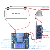
Does this look right? Excuse the amateur drawing skills. Obviously, I would not hook up the PV panel intentionally but in case of an MPP failure, I think this would be the circuit.
NOTE: Edited to remove image with incorrect wiring diagram. See the diagram by @BradCagle in the following comments.
NOTE: Edited to remove image with incorrect wiring diagram. See the diagram by @BradCagle in the following comments.
Last edited:
BradCagle
Solar Enthusiast
- Joined
- Aug 27, 2021
- Messages
- 578
Does this look right? Excuse the amateur drawing skills. Obviously, I would not hook up the PV panel intentionally but in case of an MPP failure, I think this would be the circuit.
@BradCagle
No, i'll draw it up.
Thank you so much for clarifying @BradCagle . It makes perfect sense. I was thinking the controller needed 12v but of course, it has to have the battery voltage to control it. I sure appreciate the help.
Hedges
I See Electromagnetic Fields!
- Joined
- Mar 28, 2020
- Messages
- 21,607
I don't have a scope ATM.
Here's a link to the guts of the economizer http://myelifenow.blogspot.com/2013/03/opening-up-tyco-kilovac-ev200aaana.html
Two wires from the outside, two wire to the coil.
I'd guess it is switching on and off, using coil as its own inductor. A switching current source.
BradCagle
Solar Enthusiast
- Joined
- Aug 27, 2021
- Messages
- 578
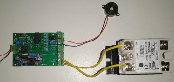
I ended up taking @crossy 's proposed solution a bit further. I had some PC boards made to make an easy build of it and added a couple more features.
A miniature SSR can provide control to an active cell balancer at the upper knee of the cell charging graph. ON at (~3.40v/cell) and OFF at (~3.35v/cell).
If the board senses average high voltage (~3.55v/cell) at the main battery +/- terminals, it shuts off the PV panel SSR and at the same time triggers a remote mounted piezo alarm as an alert until average battery voltage drops low (~2.95v/cell).
Provision for up to three PV array SSRs (all three SSRs trigger OFF or ON at the same time).
An off/on switch controls power to the board, which in turn shuts off the PV arrays. The board is protected by a 250mA resettable fuse.
The DC-DC buck converter installed in the pic below has a max 40v input. 60v buck converters are available with the same footprint for higher battery voltages.
The 40A SSR w/heatsink was the most expensive part, $13 at Amazon. All together, a very budget friendly solution. Special thanks to @crossy !!!

crossy
Solar Addict
@Davismltc Nice job, good to see my design in the flesh so to speak. 
I do like the idea of controlling the active balancer. Ours is operational all the time, I'm not sure if we are actually losing significant amounts of energy via the beast (our cells are "somewhat" worn and mis-matched), plenty of spare ports on the coulomb-counter for some controls.
I do like the idea of controlling the active balancer. Ours is operational all the time, I'm not sure if we are actually losing significant amounts of energy via the beast (our cells are "somewhat" worn and mis-matched), plenty of spare ports on the coulomb-counter for some controls.
There's an Australian fellow on Youtube, "Offgrid garage", that has newer cells. He found running an active balancer all the time was causing more imbalance, as compared to only running one at the upper knee. I think it could also depend on how low the battery is utilized before recharging, and if it's capacity is being limited by the lowest cell voltage. If the cells aren't matched very well, running a balancer all the time may be beneficial.
Roswell Bob
Solar Enthusiast
Yea. would need a minimum load. Vicor produces buck converters that are open loop. They are called intermediate buss converters.I don't think a fixed duty cycle will work great, it's not as simple as 50% duty cycle will give you half the voltage. You need to have feedback voltage loop to maintain the correct voltage because the load dictates the voltage
I guess if you know the load very well you can size the inductor/capacitor correctly, and experiment with the duty cycle to get it right. But the buck converter will be tuned only for the given load. Change the load, and if it's too small you might get full input voltage, on the output.
burgerking
New Member
I forwarded this thread to my friend/supplier who in turned posted it to a local supplier discussion forum. Unfortunately for him, said forum was mostly Daly fanbois (suppliers) and immediately reacted to the title of the video before watching the content.
My friend got kicked out of that discussion forum.
Simply put, the title of the video was insinuating Daly at fault.
Nonetheless, I learned a lot of lessons in this thread.
#1. faults can happen everywhere. be prepared.
#2. dont argue with fanbois. dont buy from fanbois.
My friend got kicked out of that discussion forum.
Simply put, the title of the video was insinuating Daly at fault.
Nonetheless, I learned a lot of lessons in this thread.
#1. faults can happen everywhere. be prepared.
#2. dont argue with fanbois. dont buy from fanbois.
BradCagle
Solar Enthusiast
- Joined
- Aug 27, 2021
- Messages
- 578
I forwarded this thread to my friend/supplier who in turned posted it to a local supplier discussion forum. Unfortunately for him, said forum was mostly Daly fanbois (suppliers) and immediately reacted to the title of the video before watching the content.
My friend got kicked out of that discussion forum.
Simply put, the title of the video was insinuating Daly at fault.
Nonetheless, I learned a lot of lessons in this thread.
#1. faults can happen everywhere. be prepared.
#2. dont argue with fanbois. dont buy from fanbois.
Yeah, the title is just wrong as this can happen with just about any MOSFET switched BMS
I checked my JBD 120A rated BMS. Its FETs are NCEP40T17A rated at 40vdc (25*C) absolute max limit for drain-source voltage.Yeah, the title is just wrong as this can happen with just about any MOSFET switched BMS
burgerking
New Member
Is this for a 12v, 24v variant?I checked my JBD 120A rated BMS. Its FETs are NCEP40T17A rated at 40vdc (25*C) absolute max limit for drain-source voltage.
Mine is a 4s (12v) model: JBD-SP04S020-L4S-120A-B-U (v 1.0)Is this for a 12v, 24v variant?
The owner's manual they sent me says operating voltage is 14.6v max.
I don't know about the 8s (24v) one.
Last edited:
Similar threads
- Replies
- 10
- Views
- 268
- Replies
- 31
- Views
- 1K
- Replies
- 8
- Views
- 694
- Replies
- 42
- Views
- 3K


