diy solar

diy solar

Why not to use Daly BMS with MPPT controllers

Bare with me here, I'm not a technician by any stretch of the imagination and I may well be wrong but, as far as I understand, if you directly connect a PV to a system with a battery connected, the system will not see PV voltage, rather battery voltage that will begin to rise as soc increases.

If that is the case, how would the relay ever see more than its trigger point of 14.4v ?
 
If the charge controller fails as described here or as a typical switching Mosfet failure (melted short between source, drain and gate), the full PV voltage is sent to the battery BMS. When battery voltage gets above 14.4, then the BMS disconnects the PV from the battery via its Mosfet switch.
At that point the voltage then rises to the the open circuit PV voltage, which in this case is high enough to fry the BMS PV disconnect Mosfet, which then lets that voltage through to the cells. That would pull down the voltage initially as it looks like a huge capacitor, but battery voltage will then climb until cell failures, fire, etc. If you do use the big 12V battery disconnect relay, when it starts to open, PV voltage will again rapidly rise to the open circuit PV voltage. That high voltage may then jump the gap. This is when the relay contacts may weld themselves.

DC relays and switches have a tougher life- the arc doesn't self extinguish as in AC power. Current and voltage both increase the required gap distance needed to stop arcing. I'm familiar with this as my custom off grid PV/power system and primary home power is 120VDC (plus 12V and 230/115 via custom inverter for the well/shop/compressor and laundry). Heavy duty 240VAC rated switches and relays used for 120VDC will fail via melt down arcing on the very first opening with just a modest 4A resistive load. It made a strong educational experience.

No such issue with sold state DC relays, or in the case of a crowbar application, an AC rated SSR. It will turn on but can not turn off as an SCR/Triac can't turn off until current flow stops. Thus they can only be used as a crowbar or "latching" relay for DC. The voltage and current ratings are very high. Amazon has one rated 440VAC, 100A for $16.
 
I've decided to take a slightly different route.

One of our low-cost (PowMr) SCCs has recently decided to not cut off when at the set voltage (it still seems to be MPPTing correctly). The first I noticed was the inverter cut off on battery over-voltage (60V on a 48V system). Luckily the BMS (yes a Daly) did it's job and the FETs survived (attached solar string is around 100v O/C although the pack never got anywhere near that probably no more than 65V).

I'm already monitoring pack voltage via a DIY monitor so I've added a HV (250V) DC 50A solid-state relay in series with the solar input of the MPPT with a battery over-voltage set point of 58V.

I'm not seeing a measurable performance change from the relay volt-drop but as with all things solar everything is a variable.
 
That's a good approach and the small voltage drop on the high voltage side is an insignificant loss.
Just make sure the heat sinked DC SSR is not too hot at the end of a deep bulk charge cycle. Some of the current ratings on China products are laughable, and they don't generally provide the on resistance so you can calculate the heat to be dissipated. I've used them for modest current applications and have had no trouble.
 
Thanks Bruce,

There's still a few things I'm struggling to get my head around in your reply. I'll start by explaining my though process again.

-The jbd BMS shuts off at 15v via it's mosfet switch. (Over voltage).

-The bmv will trigger the relay at a lower voltage of 14.4v.

This is before the BMS shuts off and is exposed to the PV voc and resulting damage to mosfets and Lifepo4 cells.

So unless you're saying the damage would occur before the battery voltage reaches 14.4v I don't understand.

- The relay would only be breaking at 14.4v, would it not?
-The relay is rated to 300a live switching and 100,000 cycles.
 
Yes, if the relay trip voltage is lower than the BMS, the the relay only sees a modest rising voltage as it starts to open. It should be OK. I didn't grok that the relay would be the first to open, thanks for pointing that out.

The monster relay is not my preferred solution because it's another switch not rated for the open circuit PV.

Switching to a BMS with a high enough voltage Mosfet, or modifiy yours it so it can handle the open circuit PV voltage, or a Crowbar SCR or high voltage DC SSR seem more appealing to me.

There are lots of ways to solve this.
 
Last edited:
I can't figgur how this wouldn't flutter on/off. I am thinking about breaking after the scc and before the batteries. With trigger above the scc and below it before the break, hunting for voltage to trigger around 0-3vdc?
 
Yes, fshan, to avoid oscillation the triggering over-voltage event must be "latched" by either the control electronics or the device...thus the use of a latching relay, or SCR type crowbar, or a cmos flip flop gate to maintain a disconnect signal to a DC SSR, or microcontroller to do the same.
 
Yes, fshan, to avoid oscillation the triggering over-voltage event must be "latched" by either the control electronics or the device...thus the use of a latching relay, or SCR type crowbar, or a cmos flip flop gate to maintain a disconnect signal to a DC SSR, or microcontroller to do the same.
With all due respect and most humbly, I just prefer (more like insist) that I personally always deenergize all safetys. If you have to pick something up for your safety to work, it will only work if you pick it up. I would rather deenergize something rather than energize something for safety. I am trying to probe the input and output of the piece of equipment in question, the scc, looking for the difference of potential to approach or equal zero and then deenergize the circuit. In a failed state the voltage will be varying, but none the less, the difference will be near zero.
 
Fshan, Crossy's nice solution meets your requirement; the SS relay is kept on until voltage gets too high, then the on signal is removed. That fits your safety philosophy, right? A small latching relay or 4000 series logic latch could break the signal to the SS relay optically isolated input. There are 100 ways to solve this; we all have our preferences. I'm for anything that will save the batteries and preferably, the BMS as well in most situations, as simply and cheaply as possible.
 
Fshan, Crossy's nice solution meets your requirement; the SS relay is kept on until voltage gets too high, then the on signal is removed. That fits your safety philosophy, right? A small latching relay or 4000 series logic latch could break the signal to the SS relay optically isolated input. There are 100 ways to solve this; we all have our preferences. I'm for anything that will save the batteries and preferably, the BMS as well in most situations, as simply and cheaply as possible.

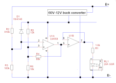
Here's a very quick and dirty driver for the SSR, fully automagic and non-destructive.

Note:- I've not actually built this as I'm driving my relay from my Arduino-based battery monitor / coulomb-counter but I've used the circuit many times in the past.

1652132294206.png
Power comes from a 60V-12V buck converter (we're bringing battery voltage to the beast, might as well use it - don't forget a fuse!) get one from AliExpress https://www.aliexpress.com/item/32833317118.html for lower pack voltages you could use a simple regulator, 7812 or similar (watch input voltage and power dissipation) or supply it from a wall-wart. We do need a regulated supply as it's used as the voltage reference.

R2 and R3 form a 10:1 voltage divider, values are for a nominal 48V pack, you can adjust the values to suit your pack https://ohmslawcalculator.com/voltage-divider-calculator

U1A along with R4, R5 and R6 form a Schmitt-trigger with thresholds of 6V and 5V if you want to adjust the thresholds / hysteresis then here is where to go https://www.random-science-tools.com/electronics/inverting-schmitt-trigger-calculator.htm

D1 is there so we can never take the input to the op-amp outside the supply rail, it doesn't like that!

U1B is simply a voltage follower/buffer to drive the relay. R1 limits the relay drive current, not strictly necessary as the relay is happy between 3V and 30V input but it saves a few mW.

How it works.
  • If the battery voltage is below 60V (junction of R2/R3 is below 6V) then the Schmitt output is high and the relay is energised (normal operation).
  • Should the battery go over 60V then the Schmitt operates and its output goes low turning off the relay and disconnecting the solar.
  • The Schmitt output stays low until the battery voltage goes below 50V at which time everything turns back on.
 
Last edited:
Nicely done, Crossy. If the line voltage is sensed BEFORE the BMS, and BEFORE the DC SSR, then this could catch the voltage going ABOVE the normal BMS battery full level when the charge controller has failed as a short and after the BMS has opened it's input Mosfet(s). The high voltage sense level must be well below the BMS disconnect mosfet rating so that the circuit and SSR have time to open before the voltage rises too far.

This would allow the circuit to continue to sense the excess voltage even after opening the DC SSR, and not cycle on and off, frying the BMS the first time it went back on with excess, unbucked high PV voltage.

For someone who doesn't already have some 12V handy to operate this, I would consider using a single micropower comparator, and dropping resistor plus ldo reguator instead of a 60 to 12V buck converter, as it could be simpler, and use no more power. You need about 3 ma to drive the opto SSR, plus less than 0.05 ma for the comparator. Wasteful but better than the buck converter operating at very low power level.
 
Yeah @BruceM there's a zillion ways of doing this.

I'm cutting the solar input to the SCC simply because the currents are smaller (less power loss in the relay volt-drop) and I happened to have a couple of suitable relays in-stock. My Arduino unit is powered by one of those little buck converters hence I know the beasties, going micro-power and a simple resistor/zener dropper would be fine. Would probably even be OK with the LM358, they're not particularly thirsty, a similar circuit I did a while back draws about 1mA.

"Battery Voltage" is sensed on the 48V bus, I've got several packs and SCCs running together so a single sense point is easy to do. My system is set to kill all the solar input when the bus voltage exceeds 58V (I may need to look at this level again).

Obviously if it does actually shut down one then has to determine why and what component has gone west :(
 
Last edited:
Fun to read about your competent and creative work, Crossy. Bravo and thanks.

Something to keep the old grey cells active, only a couple of years to go and I can retire and probably get bored witless.

Long ago I used to do electronics design for a living but I pre-date power FETs and CMOS was horribly expensive (as an apprentice we dealt with valves/tubes etc.).

As a Consultant Engineer I now have to deal with contractors who do all the fun stuff whilst I shuffle documentation and Variation Orders :(

For five years I reviewed contractor's documentation submission, drafted letter recommending (or not) acceptance.
I quit that and designed my first real analog boards for a product, much more fun. But at least I taught the contract firm a thing or two.

Vacuum tubes were addressed in some early technician classes I took. TTL was solid when I was in school and CMOS was slow, but later it passed most everything else. My early professional designs were NMOS (custom ASIC) before CMOS was competitive.
Several recent jobs involved electron optics and ion optics, which is basically vacuum tubes.

Ever touch magnetic amplifiers? They probably predate the vacuum tubes. Try them out, easy enough to get a crude one functioning.


Since I've recently been dealing with chokes, transformers, hysteresis, and saturation lately, I just implemented one.
Maybe later I'll get sample cores with optimized characteristics, hopefully figure-8 or E-core. I realized better to cancel magnetic fields than connect two kV windings to cancel voltage.
 
I'm a gray haired EE/CS myself. Formerly in military flight simulation development and some work in ICE and related development tools at Motorola.
Thanks to 30 years of MS and resulting epilepsy I'm not the sharpest anymore. Simple things take a lot more time and effort. Oddly, I now find analog design easier than software, which was once my forte. I mostly do extreme EMC work...ultra low EMI designs.
 
Yeah @BruceM there's a zillion ways of doing this.

I'm cutting the solar input to the SCC simply because the currents are smaller (less power loss in the relay volt-drop) and I happened to have a couple of suitable relays in-stock. My Arduino unit is powered by one of those little buck converters hence I know the beasties, going micro-power and a simple resistor/zener dropper would be fine. Would probably even be OK with the LM358, they're not particularly thirsty, a similar circuit I did a while back draws about 1mA.

"Battery Voltage" is sensed on the 48V bus, I've got several packs and SCCs running together so a single sense point is easy to do. My system is set to kill all the solar input when the bus voltage exceeds 58V (I may need to look at this level again).

Obviously if it does actually shut down one then has to determine why and what component has gone west :(

What Opto DC SSR 20A would you suggest? I'm looking for one as shown in your schematic above.
 
What Opto DC SSR 20A would you suggest? I'm looking for one as shown in your schematic above.

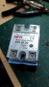
Fotek SSR-60 DD (actually a 60A unit) was the unit I used mainly because I had a number in-stock from another project. I do note that the various current ratings in this series are actually very similarly priced so going over sized isn't going to break the bank. Do get a suitable heatsink, mine doesn't get very warm but keeping the temperature down is always nice to the works.

I would certainly replace the buck converter with a simple zener-resistor regulator if were to actually build one.

90931.jpg
 
Last edited:
Thanks!!
The relay in the picture has the name spelled "FOETK"... LOL
 
Last edited:
Back
Top