diy solar

diy solar

WHY THE HEAT ?

BackTOschool

tellsteve2@gmail.com
Joined
Sep 29, 2022
Messages
44
Hello,
Can I ask for advice please?
I have a heating issue that I do not understand, My positive lead to the inverter is going above > 50deg c. (and would go higher if left)

I have 1 x 300Amp battery, with a 12v1200 watt Victron inverter.

When the inverter is near load max output at 1130 watts, I'm finding that my positive lead connecting the battery to the inverter is getting hot between the battery and fuse.
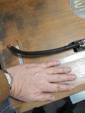
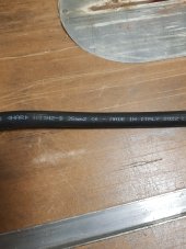
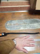
I previously used 25mm pure copper multistrand welders cable, which I have replaced with 35mm cable, my understanding it's rated to 290Amps.
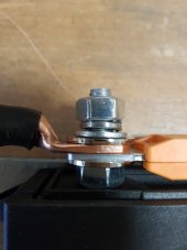
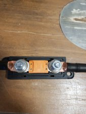
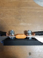
I previously used a cheap Amazon ANL 125A fuse, which I've upgraded with a Victron Energy Mega Fuse Holder and a Mega Link Fuses Current Rating: 150A

The constant test load is 106A (240v) ( 1130 watts )
The Battery is good for a consistent load of <150A
The Cable is good for < 290 Amps, and has been created with recommended pure copper lugs.

Even after the "uprating" Its still getting hot, > 45+ deg C

I have now completely removed the fuse by making a new cable straight from battery to inverter (yes I know that's not recommended) and the heat disappears!

Any idea's please?
thanks
Steve.
 
Fuses do get warm when current is high. If it is supposed to melt above 150A it will definitely not be cold at 100A.

Could also be the contact, nuts not tight enough, or maybe the crimps, but if the cable is equally hot on both sides of the fuse then it's not one bad crimp or one badly tightened nut on one side.

The cable is copper which conducts heat very well, especially when it's this thick, so the hot cable probably is just acting as a heat sink for the fuse, not being the source of the heat.
 
Last edited:
Can we see the pictures of your setup?
it sounds you have contact resistance issue?
Did you measure the Vdrops on the fuse?
Hello Bud,
Here are pictures of the fuse and cable setup. I made the cables up, ensuring everything including crimps were very tight.
the fuse holder is the Victron Energy Mega Fuse Holder, and a Mega Link Fuse Current Rating: 150A. One end from battery, other to inverter.
Steve.
 

Attachments

  • 1.jpg
    1.jpg
    80.2 KB · Views: 68
  • 2.jpg
    2.jpg
    159.3 KB · Views: 65
  • 3.jpg
    3.jpg
    146.9 KB · Views: 67
  • 4.jpg
    4.jpg
    158.8 KB · Views: 67
  • 5.jpg
    5.jpg
    173.5 KB · Views: 68
  • 6.jpg
    6.jpg
    165.2 KB · Views: 67
33.6mm = 2awg. For 150 amps it really should be 1 awg or 42-43mm.

Fuses and lugs can add a lot of resistance - that's where I get all my heat as well, but my max current is about 75 amps.

Here's the blue-sea ampacity chart, kind of the gold standard for these calcs - it's saying 50mm wire.

DC_wire_selection_chartlg.jpg


Good eye Sparky. It also looks like there is a washer under the buss bar between the stud?

The washer under is fine - what we're looking for is the contact between the lug and the fuse blade - that's fine. But yeah, they have to be tight.
 
I would sand both blade and lug surfaces with fine-grit paper and apply no-lox or equivalent. Make sure that connection is as clean as possible.
The crimps for the lugs - that may be a resistance culprit as well.
 
It looks to me the nut needs tightened more. There's a lot of gap in that split washer (more than I'm used to seeing), and it is resulting in uneven pressure.
Sorry, I did not think to explain the photos:
The photos are of the fuse removed from the system, It shows the components and order of mounting.
When it was attached and in use it was FULLY tightened, and not left finger tight as in the photos.
kind regards
Steve.
 
With high current flowing, use DMM to measure voltage across each contact. Lug to terminal, terminal to wire strands or far end of wire, between terminals of fuse, etc.
 
Last edited:
I would sand both blade and lug surfaces with fine-grit paper and apply no-lox or equivalent. Make sure that connection is as clean as possible.
The crimps for the lugs - that may be a resistance culprit as well.
Thanks for the chart, its helpful.
I'm a little confused with the wire gauge:
The Inverter states its spec as 12v 1200 watts continuous power , it does not state its amps. however If my calculations are right the amps value at 1200 watts is 100Amp.
The Inverter states in the user manual the maximum wire size is " 35 / 25 / 25mm2 / AWG2 / 4 / 4"
I'm using 35mm cable, this is the maximum designed capacity. Any thicker cable will not fit into the inverter.
so just to focus again, the 35mm cable when wired direct from battery to inverter works fine, next to no heat.
When fuse placed in line, excessive heat is generated. no heat build up is detected directly on the centre of the fuse.
  • Lugs are good, same batch and method as direct cable.
  • Cable is good, (now heat when connected directly without fuse).
  • Fuse is 150A
  • Fuse holder is new, Phoenix made quality
  • Everything is very tight.
I have no idea why heating up !!!???
kind regards
Steve.
 
I'd still suspect a problem with the short wire, then. Have you tried, as a test, bolting the two lugs that mount to the fuse together directly? Either that, or try @Hedges' voltage drop test. The latter, done right, will be completely unambiguous as to where the problem is.
 
I'd still suspect a problem with the short wire, then. Have you tried, as a test, bolting the two lugs that mount to the fuse together directly? Either that, or try @Hedges' voltage drop test. The latter, done right, will be completely unambiguous as to where the problem is.

I'd still suspect a problem with the short wire, then. Have you tried, as a test, bolting the two lugs that mount to the fuse together directly? Either that, or try @Hedges' voltage drop test. The latter, done right, will be completely unambiguous as to where the problem is.
Thanks for input,
no I have not tried either, will do. I'll learn how to do the v drop test, and complete. thanks.
 
Voltage drop test is pretty easy. Take your multimeter, set it for DC volts on the lowest range it has, and start probing the wires at various close together points. Everywhere there is any kind of connection between your probes is a valid target. You should see nearly zero everywhere, but somewhere related to that short cable will probably have .3V or so. At 50A, that's 15W of heat at that connection.
 
Back
Top