diy solar

diy solar

Why use two wires with AC?

svetz

Works in theory! Practice? That's something else
Joined
Sep 20, 2019
Messages
7,364
Location
Key Largo
This is for all you EE geeks (yeah phogandive , that includes you buddy!)

Now DC makes perfect sense to me, you put an electron on it bumps electrons all along the way until one at the end of the circuit falls off; it needs a return wire for that electron to make it back.

But AC is a frequency. Put on a few electrons, then pull a few off.

The typical household 120 AC as measured by the RMS method. But that pretty sine wave behind is running 340 volts peak to peak behind it.

Since it's put some on and pull some off, why do you need the wire for the return trip? If I had a pair of diodes, like the front of an H bridge, then when some electrons were put on it could take one path and push electrons into the circuit. When it pulls some off if could pull from the other diode pulling excess electrons out of the circuit.

I'm not saying two wires wouldn't be more efficient, having two allows for no net capacitance at any time.

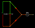
Think of it like using tidal energy; you're using the imbalance in voltage over time to accumulate charge rather than a return path for electrons to flow. It's not done now to my knowledge, but I don't see why it wouldn't work since once you have charge it would be like a DC battery. As mentioned earlier, it wouldn't be efficient - but I don't see why it wouldn't work. Here's a circuit diagram that's at least fooled the simulator into thinking it would work...

1-wirePower.PNG
 
In really basic terms, AC reverses direction, the frequency referred to is how often it does it. Without two wires there is no path for the electrons to move. By using transformers it is quite easy to change the voltage of AC. A transformer depends on the collapsing field around a wire or coil to change the voltage. The ignition coil in a car is a transformer but, it depends on the points, or some electronic device, to switch the primary winding in the transformer (coil) quickly to produce the field collapse.
The alternator in a car produces AC which is then converted to DC by means of a diode bank.
Hard to explain in a few words how the old automotive generators work.
Not sure what much of the other stuff you wrote about,
 
Hey PhoganDive! Glad to see you here!
I don't see that it has to be connected. When the voltage is +170v electrons must flow through the one diode, and at -170v they must flow out the other, at least until the voltage balances... so the cap should charge should it not?

SomeWhereInUsa: I agree that the circuit as is would be pretty hard on the generator, but a mirror of the circuit on the other side should balance it out.
 
Hey Rider! Great to see you over here! It sounds like you're dubious the cap would have a charge? Can't say that I blame you.
 
Not quite. I think the cap will have a charge, but only if measured with a two-wire meter across the terminals of the cap. What I'm questioning is the proposed potential on the right side of those caps. There's only voltage if it's referenced against another line/point/reference/etc. A single wire has no potential when referenced against itself. It's not usable energy.
 
A piddlingly small current will flow until the capacitance of the entire thing is satisfied. Forget the diodes, forget the depicted capacitor, they aren't seen as discrete components in this configuration. The entire circuit is one side, the air is the dieletric, and the other side of that AC input, which is not shown, is the other side.
 
With a single wire, the only thing that will happen is the electrons already there will gain some potential energy from the voltage of the AC source. If you had a method of carrying the charge, it would build up....but it would be static electricity (that's the way a Van de graaff generator works)*. You still need two wires to complete the circuit to let current flow.


* Many years ago, I worked at High Voltage Engineering, a company co-founded by Robert Van De Graaff. :)
 
Interesting you should mention Tesla as he figured out how to transmit power using a single wire with no return:

At the end of the 19th century, Nikola Tesla demonstrated that by using an electrical network tuned to resonance it was possible to transmit electric power using only a single conductor, with no need for a return wire. This was spoken of as the "transmission of electrical energy through one wire without return"

Reference: https://en.wikipedia.org/wiki/Single-wire_transmission_line
 
Same scenario (i.e., AC over a single wire), just not my silly and misleading half H bridge scenario. ;)
 
Lots of SWER around here. Sure there's only one wire, the return is the earth and the load, the transformer, sits between the wire and the earth. Long earth rods are staked at the transformer. There is a clearance area around the rod where no other cabling is permitted, phone lines and the like. Depending on the soil type there may even be a fence around the entire thing due to the risk of ground rise.

Defintely not the same scenario :)
 
So, if it can be done with one wire, how about no wires?

Tesla was working on wireless transmission and built the Wardenclyffe Tower to "beam" power to locations.
250px-Tesla_Broadcast_Tower_1904.jpeg


The World Wireless System was a turn of the 20th century proposed telecommunications and electrical power delivery system designed by inventor Nikola Tesla based on his theories of using Earth and its atmosphere as electrical conductors. He claimed this system would allow for "the transmission of electric energy without wires" on a global scale[1] as well as point-to-point wireless telecommunications and broadcasting. He made public statements citing two related methods to accomplish this from the mid-1890s on.

Tesla's demonstrations of wireless power transmission at Colorado Springs consisted of lighting incandescent electric lamps positioned nearby the structure housing his large experimental magnifying transmitter, with ranges out to 1,938 feet (591 m) from the transmitter. There is little direct evidence of his having transmitted power beyond these photographically documented demonstrations. He would claim afterwards that he had "carried on practical experiments in wireless transmission". He believed that he had achieved Earth electrical resonance that, according to his theory, would produce electrical effects at any terrestrial distance.
 
Sorry, thought it was SWER. Didn't actually read it :unsure:

It instead refers to capacitance and tuned circuits. Now where did I see someone mention the overall capacitance of your circuit as a whole would permit piddly current to flow .... ;)
 
Sorry, thought it was SWER. Didn't actually read it :unsure:

It instead refers to capacitance and tuned circuits. Now where did I see someone mention the overall capacitance of your circuit as a whole would permit piddly current to flow .... ;)
That's why I "liked" your post! Had you gone to high frequency you'd have had it :cool:
 
Tesla's wireless experiment was responsible for the explosion at Tunguska.


:p
Okay, let's not go crazy! Tunguska was in 1908, well before this. Obviously that had to be from Marconi's experiments.

UPDATE: OOPS! Wardenclyffe was built in 1901. I was thinking 1917 which is when debts forced it to be scrapped... Okay... you might be right!
 
Last edited:
Back
Top