diy solar

diy solar

AC coupling: Victron Multiplus + HoyMiles microinverter ?

Manfredi

New Member
Joined
Apr 17, 2022
Messages
19
Hi ,
i want to extend somewhat the capacity of the PV plant, with a remote group of panels located far away from main PV string and the plant core with 25kWh batteries, hybrid inverter and MPPT chargers. Main plant has 8kW of panels and uses Victron 150/70 and Morningstar Tristar MPPT 150/60 as solar chargers. The hybrid inverter is a cheap chinese toroidal low frequency inverter the (RP6000) rated at 6kW, 18kW surge. The plant will serve two houses, so I will need to add a second inverter, further battery and PV capacity.

I want to use two Hoymiles HM-1500 microinverters to add 6x 415w panels, attaching them directly to the AC side of the offgrid plant. I read that HoyMiles can do frequency shifting, to communicate with other inverters and agree on the amount of AC power to generate and put in the AC circuit.

I read somewhere that Victron Multiplus II, can also implement this "frequency shifting" mechanism on the AC side, so the idea is to add one or two Multiplus 5000VA to the core plant, configuring the Victron to eventually charge the batteries (max 70A DC charging power for each Multiplus), getting extra power from the AC side when available. The chinese toroidal, supposedly not able to do frequency shifting, will be moved to second house with separated AC circuit.

Will this idea work ? Microinverters are getting cheap and efficient, and being able to partially recharge the batteries from extra power generated in the AC side of circuit, is an interesting scenario for me but also others with offgrid plants. Is there a Victron expert that can comment and suggest a minimum configuration to implement this?

Regards, Ugo
 
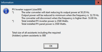
Victron has a PV inverter assistant to allow for AC coupling. You program the various frequency set points to control the PV inverter. Here's an output of the assistant default config:

1708956944236.png

You would need to know the PV inverters frequency shift points.

Here's a user with an AC coupled installation:

 
@sunshine_eggo Thank you for the precious suggestion. From what you say, it seems I have to configure a Victron ESS (Energy Storage Assistant) for everything in this AC Coupling to work smootly. This would oblige me to buy a Cerbo GX to access VRM and configure the ESS. But I am not sure this will be enough or will be needed to realize my desired scenario.

If I decide to use all HoyMiles as micro-inverters, they will communicate between themself using a data bus, and do not need any frequency shifting to trim down their output when there is insufficient AC load. The island (offgrid) frequency will be established by the hybrid inverter, can be a Victron Multiplus, but even a "dumb" inverter, like my LF toroidal or an HF hybrid, is OK to establish the working frequency of the island, and the microinverters will adapt to it. In absence of any direct data communication between islanding inverter and microinverters, I suppose that when there is PV power available, the microinverter will simply raise the AC voltage to offload the main inverter, when it has no power will lower the voltage to match the available PV power. All this happens without any communication, apart the AC voltage, between the hybrid inverter and the microinverters.

The key question in this scenario is the following: how can the Victron (or the ESS) decide there is excess AC power available, so he can activate the battery charging function ? This seems to involve some metering, done in the AC leg, and also checking if batteries are already full. Clearly, if the solar charger 150/70 is already in FLOAT mode, there is no need to activate the Multiplus charging function, while it could be activated if 150/70 is still in BULK mode.

It seems that activating correctly the AC coupling charge function, requires a careful consideration of the DC charging status, and is not a trivial configuration.

Bye, Ugo
 
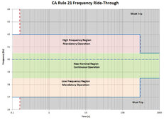
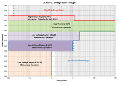
PV Grid tied inverters frequency shifting points for PV GT inverter power reduction have changed with CAL rule 21. You have to check each model PV GT inverter to see what it does.

Original Sunnyboy did not reduce power until AC freq hit 61 Hz and linearly drops its output power to 62 Hz where it shuts down. Grid almost never goes above 61 Hz so it pretty much ensured you would not have PV cutback when grid connected.

Cal21 ruling has brought the start of power reduction frequency down under the statistical reality that when grid is running higher than 60.0 Hz the grid is likely experiencing lighter than expected consumption demand and does not really want more power from residential PV pushes. 62 Hz still remains as total PV shutdown frequency. Higher grid voltage variation from nominal usually correlates with higher grid frequency, both related to lighter than expected grid demand.

The most common time of day you will see higher freq/voltage from grid is 8-10 pm when grid demand starts to drop off faster than utilities expected. Most of the year the sun has gone down so there will not be much PV power push to deal with.

Cal21 freq ride-through.jpg
Cal21 voltage ride-through.jpg
If I decide to use all HoyMiles as micro-inverters, they will communicate between themself using a data bus, and do not need any frequency shifting to trim down their output when there is insufficient AC load. The island (offgrid) frequency will be established by the hybrid inverter, can be a Victron Multiplus, but even a "dumb" inverter, like my LF toroidal or an HF hybrid, is OK to establish the working frequency of the island, and the microinverters will adapt to it. In absence of any direct data communication between islanding inverter and microinverters, I suppose that when there is PV power available, the microinverter will simply raise the AC voltage to offload the main inverter, when it has no power will lower the voltage to match the available PV power. All this happens without any communication, apart the AC voltage, between the hybrid inverter and the microinverters.

The key question in this scenario is the following: how can the Victron (or the ESS) decide there is excess AC power available, so he can activate the battery charging function ? This seems to involve some metering, done in the AC leg, and also checking if batteries are already full. Clearly, if the solar charger 150/70 is already in FLOAT mode, there is no need to activate the Multiplus charging function, while it could be activated if 150/70 is still in BULK mode.
You are not understanding why frequency shifting is necessary. Generated power must always be consumed as it is made. Either by AC loads, battery charging, or pushed to grid.

If you lose grid and you don't have enough AC loading to consume PV generated power, the only place left to push the power is into batteries.

When grid is absent, you must regulate PV GT inverter output to keep control, and you never know when grid might drop out so inverter must be always ready to handle excess PV power.

Worse case situation is when you have no grid to push to and you switch off a large house AC load suddenly leaving a lot of excess PV power for inverter to deal with. Freq shifting takes a few seconds to react so battery must absorb the excess PV power until PV GT inverter receives freq shifted AC from hybrid inverter to reduce their output.

If the battery is already too fully charged the inverter DC input voltage may rise beyond maximum limit causing inverter to shut down to save itself. Most hybrid inverters with AC coupling capability will not allow battery to be fully charged when AC coupling is enabled to keep a safety margin for PV power absorption.
 
Last edited:
@sunshine_eggo Thank you for the precious suggestion. From what you say, it seems I have to configure a Victron ESS (Energy Storage Assistant) for everything in this AC Coupling to work smootly. This would oblige me to buy a Cerbo GX to access VRM and configure the ESS. But I am not sure this will be enough or will be needed to realize my desired scenario.

No. ESS should be avoided unless you NEED full grid interaction.

The PV Inverter assistant does not require either ESS or a Cerbo. It requires installing the configuring the assistant and connecting the outputs of the MP and the micros.

If I decide to use all HoyMiles as micro-inverters, they will communicate between themself using a data bus, and do not need any frequency shifting to trim down their output when there is insufficient AC load. The island (offgrid) frequency will be established by the hybrid inverter, can be a Victron Multiplus, but even a "dumb" inverter, like my LF toroidal or an HF hybrid, is OK to establish the working frequency of the island, and the microinverters will adapt to it. In absence of any direct data communication between islanding inverter and microinverters, I suppose that when there is PV power available, the microinverter will simply raise the AC voltage to offload the main inverter, when it has no power will lower the voltage to match the available PV power. All this happens without any communication, apart the AC voltage, between the hybrid inverter and the microinverters.

An AC coupled inverter MUST be capable of frequency shifting and charging from the PV inverter output. GT inverters, micro or string, do not manage themselves. They will output whatever the PV can deliver unless they are told to do otherwise by frequency shifting. If your loads are ALWAYS greater than the PV inverter output, then it's not an issue, but if they PV inverter output EVER exceeds loads, you will have a problem - shutdown at the least, damaged equipment at the worst.

EDIT: Somehow I missed @RCinFLA's post. Please listen to him.
 
@sunshine_eggo

I suppose that when there is PV power available, the microinverter will simply raise the AC voltage to offload the main inverter, when it has no power will lower the voltage to match the available PV power.
Where do you think the power goes if there is full PV power, not enough loads and the battery is full?
 
The plant will serve two houses, so I will need to add a second inverter, further battery and PV capacity.
Put all the batteries on ONE inverter. Having two inverters (that are not working in parallel) with batteries that work together are a problem. At any point in time, which inverter supplies power from its battery?

Two inverters with batteries on separate circuits is fine.
 
In grid-tied systems the excess power goes to the grid, eventually being/not being paid by the utility. In offgrid system, you need to set a max voltage allowed to the micro-inverter to raise the voltage. If the isalnding inverter is set to 230V, an acceptable limit could be to raise to 240V.

I hope that an offgrid inverter of LF type (those with transformer) will NOT get damaged if the secondary is subject to an AC voltage within +-10% of nominal value. If the hybrid inverter sees no load request (beacuse loads are fully powered by microinverters) it will simply not consume DC power for DC-AC conversion, and all available PV power will go into the batteries until they are 100% full. This is my ideal viewpoint !

When batteries are full, the excess PV power in the microinverter leg goes nowhere and is simply lost, the same that happens with solar chargers when 100% battery voltage is reached and you are at the end of float phase.

Anyway, speaking of batteries in a hybrid plants, where most of charging is done in DC by solar MPPT charger, is incorrect: DC batteries are not seen directly by microinverters, they can be accessed only indirectly if the hybrid inverter is configured to activate the AC->DC charging funtion.

Honestly, I think that is not worth the effort charge the batteries from excess PV power in the AC leg of plant: this task can be left to the DC side of the plant.

I never installed microinverters in an offgrid plant, so it is possible I am too optimisting about the potential dangers of this configuration: it would be interesting to get feedback from people who has done or studied in detail this configuration.
 
As long as that AC Circuit is not on a circuit with any other inverter that will island when grid is down.
Both houses will have ATS Automatic Transfer Switches: so the load will be 100% offgrid or 100% ongrid. This will eliminate any issue with public grid operators.
 
When batteries are full, the excess PV power in the microinverter leg goes nowhere and is simply lost, the same that happens with solar chargers when 100% battery voltage is reached and you are at the end of float phase.

That's a fundamental misunderstanding of GTI. GTI is a current source and will raise the AC voltage as high as it can to push max current. Power will go somewhere and not just lost.
 
PV Grid tied inverters frequency shifting points for PV GT inverter power reduction have changed with CAL rule 21. You have to check each model PV GT inverter to see what it does.

Original Sunnyboy did not reduce power until AC freq hit 61 Hz and linearly drops its output power to 62 Hz where it shuts down. Grid almost never goes above 61 Hz so it pretty much ensured you would not have PV cutback when grid connected.

Cal21 ruling has brought the start of power reduction frequency down under the statistical reality that when grid is running higher than 60.0 Hz the grid is likely experiencing lighter than expected consumption demand and does not really want more power from residential PV pushes. 62 Hz still remains as total PV shutdown frequency. Higher grid voltage variation from nominal usually correlates with higher grid frequency, both related to lighter than expected grid demand.

The most common time of day you will see higher freq/voltage from grid is 8-10 pm when grid demand starts to drop off faster than utilities expected. Most of the year the sun has gone down so there will not be much PV power push to deal with.

View attachment 198539
View attachment 198543

You are not understanding why frequency shifting is necessary. Generated power must always be consumed as it is made. Either by AC loads, battery charging, or pushed to grid.

If you lose grid and you don't have enough AC loading to consume PV generated power, the only place left to push the power is into batteries.

When grid is absent, you must regulate PV GT inverter output to keep control, and you never know when grid might drop out so inverter must be always ready to handle excess PV power.

Worse case situation is when you have no grid to push to and you switch off a large house AC load suddenly leaving a lot of excess PV power for inverter to deal with. Freq shifting takes a few seconds to react so battery must absorb the excess PV power until PV GT inverter receives freq shifted AC from hybrid inverter to reduce their output.

If the battery is already too fully charged the inverter DC input voltage may rise beyond maximum limit causing inverter to shut down to save itself. Most hybrid inverters with AC coupling capability will not allow battery to be fully charged when AC coupling is enabled to keep a safety margin for PV power absorption.
My plant is offgrid, with ATS to get back to grid if batteries are below 10%. So all regulations for grid-tied plants are not applicable in my case.
If I install microinverters, they are certainly compatible with grid backfeeding, up to 800W in Italy, without need to install a utility bidirectional meter. Other countries could have different regulations.
 
That's a fundamental misunderstanding of GTI. GTI is a current source and will raise the AC voltage as high as it can to push max current. Power will go somewhere and not just lost.
No grid tied inverter can raise the voltage beyond 253V AC, that is 230V + 10%. At 253V AC the GTI will shut down automatically.
 
No grid tied inverter can raise the voltage beyond 253V AC, that is 230V + 10%. At 253V AC the GTI will shut down automatically.
Depends on the config, most GTI don't shutoff at 253V. UL1741/IEEE1547 default is 264V and up to 288V is possible. Device/load damage and/or inverter protection shutoff could occur by then. Also, any GTI shutoff/curtailment for out of range frequency/voltage takes a while to take effect. Voltage in an island grid with surplus power (e.g. large load turn off) can go well above the valid range within a single AC cycle.
 
Last edited:
Put all the batteries on ONE inverter. Having two inverters (that are not working in parallel) with batteries that work together are a problem. At any point in time, which inverter supplies power from its battery?

Two inverters with batteries on separate circuits is fine.
Battery are in common, such as the solar chargers and the PV plant. The two inverter are simply two loads taking DC power from same battery pool, i do not see any problem in this. The AC circuit of the two houses are completely independent, and both houses have an ATS: they are 100% offgrid or 100% on grid.
 
You're clearly not interested in actual advice. Go do what you want. Let us know how it goes.
I will accept the advice that I can understand clearly.

SUMMARY UNTIL NOW

From the discussion done until now, it seems is unsafe to rely on any self-limitation in power generated from the micro-inverter. If this is the situation, and given my plant is offgrid and cannot send the excess AC power into an infinite sink like the public grid, it appear unsafe to install any microinverter of any power.

The minimum load of my house can be as low as 150W, many times lower than the HoyMiles HM1500 that I was considering, can put out up to 1.5kW AC.

To maintain the idea of a microinverter leg, the only possibility seemed to me, to introduce a frequency shifting equipment (the Victron Multiplus) instructing all the microinverters to stop producing power if there are no load and batteries are full. But measuring this condition (no load, battery 100% full) is easy to write but could be very complex to put in practice, and transient conditions, like on/off of large loads, could harm even a correct configuration.

At this point, the whole idea of an hybrid offgrid plant incorporating a microinverter section, seems at risk.

Will a white knight save me ?

Bye
 
Last edited:
But measuring this condition (no load, battery 100% full) is easy to write but could be very complex to put in practice, and transient conditions, like on/off of large loads, could harm even a correct configuration.
This is why Victron has the 1:1 island grid AC coupling requirement. The inverter and battery must be able to handle full GTI power when the battery is not full to ensure no issue with transients. Victron needs to be configured to start frequency shift well before the battery gets full (e.g. 90-95% SOC) so there is plenty of safety buffer/margin.
 
Hi,
to complete the info in this apparently hot and flame-prone topic, there is a good YT video from Off Grid Garage, Andy from Australia, that shows that micro-inverters can definetely work with Victron Multiplus in off-grid configuration. This is the info I asked for in the beginning.


The video is titled "Charging my battery from almost anywhere with this Grid-Tie Micro Inverter and the Victron Multiplus" when there is no grid, that is with an off-grid system. According to Andy, AC coupling is possible with any inverter and micro-inverter supporting the UL 1741-SA standard and properly configured.

There is some debate on the max total power of the microinverters, also called the Victron 1:1 rule: if 100% (=1) is the nominal power of the main inverter (5000VA for the Multiplus 5000/48), or its DC-charging capability, that is somewhat lower at around 3.5kW (70A x 51.2V). According to Andy, the max power of AC-coupled micro-inverters is 5000VA and not 3500VA as explained here:

See the Victron documentation here: https://www.victronenergy.com/live/ac_coupling:start

Andy shows also how to do the configuration in VRM. I consider this video very useful. In case the batteries are full (or get detached from their BMS for OVP Over Voltage Protection), the Victron will shutdown completely, eliminating the local micro-grid and the micro-inverter will stop working.

There are many grid-tie inverter that support the UL1741-SA standard of frequency shifting: Victron, Sol-Ark, Outback, SMA and many others.

There is one comment about a possible AC over-voltage when the micro-grid is shut down due to 100% capacity reached or BMS protection on batteries. The commenting user did not provide info on the inverter used to control the micro-grid, nor the micro-inverter used. To prevent frying voltage sensitive equipments, installing a reliable OVP device seems a prudent choice.

Ugo
 
For those interested in AC coupling between Victron and Enphase micro inverters, there is a specific lesson from Enphase Energy Services here:

Enphase AC-Coupled to Victron Multiplus-ii or Quattro 20230517​


The main points of this lesson are:

1) in AC-coupled systems, IQ7A Micro inverters are connected to the AC output on the Victron Multiplus or Quattro Inverter.
2) When PV is producing, it will supply power to the essential loads, while the excess power will be used to charge the battery and potentially export power to the grid once battery is fully charged
3) Victron 1.0 rule factor. The peak power of all the Micro Inverter must be equal or less than the VA rating of the Victron Inverter. For example, an 8000VA Quattro will support up to 8000 Watts Micro Inverter (Andy was right, the VA has to be taken as reference, not the charging capacity).
4) You need significant battery capacity if you want to take full advantage of this configuration in offgrid. But, if battery capacity is small, you may still connect the balance of the PV on the non backup side as a normal grid-tied connection. Enphase recommendeds a battery size of no less than 5 kWh for each 1kW of PV (for lead acid), or 1.5kW of PV (for Lithium).
5) You must configure ESS Assistant on the Victron , with frequency shifting enabled and frequency range adjusted. Despite different country regulations, there is no harm in starting power trim at 50.2Hz (for Europe) given the inverter will anyway continue increasing the frequency until the micro inverter will trim down to the required power level.
6) The correct grid profile must be selected in Enlighten for Enphase.

The micro inverters can be connected on A) the GRID side of inverter or B) the BACKUP side (uninterruptable loads) of the inverter. The frequency shifting mechanism works only on the BACKUP side, and in this case the PV power of micro inverters is always self consumed. If the micro inverters are connected to the A) side, the is the grid input side, no frequency shifting mechanism will be available, and the PV excess power will be put on to the grid. In the B) configuration, all the PV power produced by micro inverters will go to the battery or the uninterruptable loads or both, and Victron will use the frequency shifting to exactly regulate the amount of PV power produced, avoiding overcharging the batteries or exceeding the battery interface power.

While not an easy configuration, the Victron + Enphase seem a tried and tested one, offering significant advantages, and is officially supported by Enphase. I suppose that other quality micro inverters, like the HoyMiles, could benefit of the same configuration, which seems a powerful one.
 
Back
Top