You are using an out of date browser. It may not display this or other websites correctly.
You should upgrade or use an alternative browser.
You should upgrade or use an alternative browser.
Will it work? Supplementing off grid inverter/battery with on grid PV inverter in one system.
- Thread starter apctjb
- Start date
zanydroid
Solar Wizard
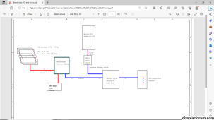
That sounds correct, the manufacturer instructions says dedicated breaker and that also makes the math sane wrt how much current can make it onto the circuit.the plan is to use the load, aka "critical load panels" as the AC-combiner/distributor, from multiple micro strings via each string's own breaker into a subpanel, the load (EVSE in this case) is tapped with its own breaker, the AIO provides the grid-forming AC and varies current flow according to the effective sub-panel load demand
zanydroid
Solar Wizard
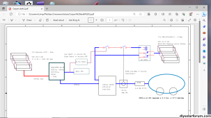
How does the AIO know to turn on the charger and absorb the extra solar? Or is the idea the extra solar only ever comes on when EVSE is on.from this discussion, draft 2 with added load current sensor/switch, to disconnect the micros at a low-amp threshold. It addresses the random charging plug-in/out and charge tappering off.
...thoughts... ?
the other unknown right now is whether those SPR-205 Sunpower panels require positive ground.
View attachment 170228
I’m not sure whether there will be power flow into the AIO. There are two parallel loads for the microinverter, the car and the AIO.
the AIO just stays on, grid-forming 240vac at the sub-panel, powered from solar day-time and 48vdc battery night time. The micros are on when the 48v battery pack is sufficiently high SOC, and obviously when sunny. The two parallel power source into the sub-panel are from the AIO & micros, the EVSE is a load.How does the AIO know to turn on the charger and absorb the extra solar? Or is the idea the extra solar only ever comes on when EVSE is on.
I’m not sure whether there will be power flow into the AIO. There are two parallel loads for the microinverter, the car and the AIO.
Plug-in to charge an EV at night would operate until reaching 48v pack is low, when the AIO would shut-off inverting.
Upon sun shining, AIO charges the 48v and starts producing 240vac. A potential problem here is insufficient capacity/production buffering causing unstable AIO on/off. Have to see if there's a Vbatt threshold to start 240vac production.
One work-around is to set the EV to charge day-time only, ... and then there are those cloudy days
cs1234
Solar Wizard
- Joined
- May 9, 2022
- Messages
- 2,302
How does something like the Sol-Ark or EG4 18kwpv know when it's safe to turn the generator relay back on for AC coupling to start / resume when the grid is down or disabled? Does it have a setting where you told it how much AC coupling is available at max sunshine? Or does it sense how much is there before turning the relay back on somehow?
zanydroid
Solar Wizard
OK. Regardless of what control scheme you use, there is nothing in this setup that ensures no power goes into the AIO. There isn’t an “AC diode” in the AIO to block power from flowing back in. An AC coupling capable AIO is engineered to tolerate this (presumably by setting up as a charger).the AIO just stays on, grid-forming 240vac at the sub-panel, powered from solar day-time and 48vdc battery night time. The micros are on when the 48v battery pack is sufficiently high SOC, and obviously when sunny. The two parallel power source into the sub-panel are from the AIO & micros, the EVSE is a load.
Plug-in to charge an EV at night would operate until reaching 48v pack is low, when the AIO would shut-off inverting.
Upon sun shining, AIO charges the 48v and starts producing 240vac. A potential problem here is insufficient capacity/production buffering causing unstable AIO on/off. Have to see if there's a Vbatt threshold to start 240vac production.
One work-around is to set the EV to charge day-time only, ... and then there are those cloudy days
I don’t understand what the SoC threshold is for.
the micros are the only other power source, and they are connected only when an EV is plugged in with sufficient demand. The high SOC cut-off turns off the micros to make sure they never produce more than the EV is pulling. The low SOC threshold turns on the micros back on.OK. Regardless of what control scheme you use, there is nothing in this setup that ensures no power goes into the AIO. There isn’t an “AC diode” in the AIO to block power from flowing back in. An AC coupling capable AIO is engineered to tolerate this (presumably by setting up as a charger).
I don’t understand what the SoC threshold is for.
zanydroid
Solar Wizard
the micros are the only other power source, and they are connected only when an EV is plugged in with sufficient demand. The high SOC cut-off turns off the micros to make sure they never produce more than the EV is pulling. The low SOC threshold turns on the micros back on.
There are two power sources - the AIO inverter and the microinverters. By design the microinverters will not backfeed each other in an unsafe way so we can consider them as one source.
The SoC seems designed with the assumption that the AIO will do something with its charger (and it's only able to do this at a low enough SoC. What is the behavior that you expect?
Remind me again how you had bench tested this combination? (with a thread this long I don't know where that post was)
I don't believe those have a setting for how much AC coupling there is. They tell you to never AC couple something capable of outputting more than the charging current supported by the AC charger and battery. As such, once the SoC drops below the level where the battery is eligible for CC at that charge current, then it is safe to turn the relay back on.How does something like the Sol-Ark or EG4 18kwpv know when it's safe to turn the generator relay back on for AC coupling to start / resume when the grid is down or disabled? Does it have a setting where you told it how much AC coupling is available at max sunshine? Or does it sense how much is there before turning the relay back on somehow?
There should not be any back-feed to AIO. The AIO simply diverts excess production (from the DC-PVs) to charge the battery, up to the float voltage set point. It pulls from battery as needed to meet load. My bench test consisted a 48vdc pack, an AIO without AC-IN (MPP), an M215, feeding the grid. There were 2-PV configuration, the DC-PV feeds the AIO PV-inputs. The other PV connected directly to the M215 then to 240vac grid. The purpose was to determine whether the AIO AC-OUTPUT was clean enough for the M215 to turn on and perform grid-tie feed. I tried with 3-different M215/M250 and was pleasantly suprised they all grid-tie fed. I could gen up a quick block diagram if that would help. Thank you so much for the discussion and comments, really don't like smokeThere are two power sources - the AIO inverter and the microinverters. By design the microinverters will not backfeed each other in an unsafe way so we can consider them as one source.
The SoC seems designed with the assumption that the AIO will do something with its charger (and it's only able to do this at a low enough SoC. What is the behavior that you expect?
Remind me again how you had bench tested this combination? (with a thread this long I don't know where that post was)
edit: I typed incorrectly, the micros were not feeding the grid with the AIO, as the AIO can not grid-tie. The initial bench test was in total off-grid. I did another test with several salvaged micros with grid-tie feed, without the AIO. Sorry for the confusion.
Last edited:
zanydroid
Solar Wizard
Block diagram would help.
What loads did you connect during testing?
It might be good to add a clamp meter test point to see how much power is being pushed from the M215, or use Envoy to pull the stats. Clamp meter would give more real time info.
What loads did you connect during testing?
It might be good to add a clamp meter test point to see how much power is being pushed from the M215, or use Envoy to pull the stats. Clamp meter would give more real time info.
timselectric
If I can do it, you can do it.
- Joined
- Feb 5, 2022
- Messages
- 18,637
As long as the load can consume everything that the micro inverters produce. It will work fine and safely.
The problem is when something goes wrong and it doesn't.
These are the "what if's" that must be controlled, at all cost.
The problem is when something goes wrong and it doesn't.
These are the "what if's" that must be controlled, at all cost.
that is exactly the intention for the two trigger thresholds, but design/intention are usually not 100% fool-proof until actual fabrication.As long as the load can consume everything that the micro inverters produce. It will work fine and safely.
The problem is when something goes wrong and it doesn't.
These are the "what if's" that must be controlled, at all cost.
quick & dirty block. A 900-w resistive heater was used as load. A clamp meter was used to measure current, and the readings were as expected. This bench test was done last year to confirm the MPP AIO can turn on a micro. Planning to repeat with recently ordered PowMr AIO soon.Block diagram would help.
What loads did you connect during testing?
It might be good to add a clamp meter test point to see how much power is being pushed from the M215, or use Envoy to pull the stats. Clamp meter would give more real time info.
Previous post was edited, correcting that the micros never grid-tie with the AIO

zanydroid
Solar Wizard
Thanks. How do the AIO and microinverter agree on how much power each of them will output? Somehow with your bench test, something reasonable happened. Maybe what the AIO sees is the load - microinverter. The microinverter will always want to output as much power as it has. Would doing something like limiting the amount of AC output current on the AIO be a good idea or even needed?
I assume you are using a current switch that is low latency/basically fully analog or digital gates?
I wonder if adding a dimmer on the heater to vary the heat would be a good idea to test some intermediate scenarios.
(Variac might keep the power factor more realistic than using a dimmer, not sure. Someone smarter than me should chime in)
the load of 900-w totally overwhelmed the micro production, which maxes out ~200-w. The AIO made up the deficit from its solar + battery. The AIO automatically adjusts the AC-output current. Please elaborate on the current switch ? didn't really use one.Thanks. How do the AIO and microinverter agree on how much power each of them will output? Somehow with your bench test, something reasonable happened. Maybe what the AIO sees is the load - microinverter. The microinverter will always want to output as much power as it has. Would doing something like limiting the amount of AC output current on the AIO be a good idea or even needed?
I assume you are using a current switch that is low latency/basically fully analog or digital gates?
I wonder if adding a dimmer on the heater to vary the heat would be a good idea to test some intermediate scenarios.
(Variac might keep the power factor more realistic than using a dimmer, not sure. Someone smarter than me should chime in)
zanydroid
Solar Wizard
the load of 900-w totally overwhelmed the micro production, which maxes out ~200-w. The AIO made up the deficit from its solar + battery. The AIO automatically adjusts the AC-output current. Please elaborate on the current switch ? didn't really use one.
OK, that makes sense. I’m not sure how this connects to the SoC logic you had in the final version. Sounds like that SoC logic is meant to help the helper AIO charge as much as possible. I feel like it’s not for safety (why not just keep the microinverter on all the time?). While the current switch logic is for safety.
How would you determine the safe ratio between maximum microinverter output and EVSE load?
Not sure what the idealized circuit model is for the AIO and microinverter to model d behavior in different scenarios
I mean current switch for your final, production version. I feel the faster it responds the less likely something weird will happen. If it’s a fraction of the AC cycle or similar to the response speed of the microinverter it’s probably fine. If you use a PLC it’s probably going to be slower than the microinverter
the SoC logic: micros OFF @high Soc/ON @low SoC, is to ensure the load (EVSE) exceeds the micros production. The thinking is that the AIO battery is drawn to help the micros, the AIO constantly adjusts between charging/draining as a function of the output load, thus acting as a buffering.OK, that makes sense. I’m not sure how this connects to the SoC logic you had in the final version. Sounds like that SoC logic is meant to help the helper AIO charge as much as possible. I feel like it’s not for safety (why not just keep the microinverter on all the time?). While the current switch logic is for safety.
the current switch logic: micros OFF @low EVSE current (or unplugged EVSE).
the safest bet is to set the low EVSE current cut-off greater than the micros' max current, but it's TBD for maximum solar production.
Have to think more about the current switching speed, doesn't seem to be an issue at the moment
possible battery voltage (SoC) detector:
possible current detector:
How would you determine the safe ratio between maximum microinverter output and EVSE load?
Not sure what the idealized circuit model is for the AIO and microinverter to model d behavior in different scenarios
I mean current switch for your final, production version. I feel the faster it responds the less likely something weird will happen. If it’s a fraction of the AC cycle or similar to the response speed of the microinverter it’s probably fine. If you use a PLC it’s probably going to be slower than the microinverter
An Off-grid type of inverter cannot be used in the proposed configuration which is called AC Coupling.
Not exactly true , quite a few higher end off grid inverters can AC couple, including victron, Xw , outback
AC-coupling and the Factor 1.0 rule [Victron Energy]
thought to update, though sorta hi-jacked this thread. So got my cheapy AIO 240 (PowMr 5.5K48) on the bench, first thing was to remove the N-G screw thus allows split-phase generation via transformer. Been running various functional tests, so far so good. Was glad the AC-OUT can turn on an old M215. The test load is a 100-w incandescent bulb, with a router speed controller to vary the draw. The AIO can throttle battery consumption as expected with variable load. What was/is surprising is that the 48v battery gets charge from the AC-OUT line, with excess power produced by the M215 micro. Another surprise finding yesterday is the M215 doesn't need the Neutral to work.If you want to go cheap AIO with DC would be way cheaper and simpler, and the only smoke potential is from using a dodgy AIO which can’t be terrible given how few forum members have died from using them. Unless the M215 were free. But you need an AIO anyway to grid form.
I suspect a cheap HF inverter would be perfectly fine with a car charger load
Next on deck is to tap the HVDC from an EV, without smoke
Similar threads
- Replies
- 1
- Views
- 90
- Replies
- 1
- Views
- 118
- Replies
- 4
- Views
- 227
- Replies
- 37
- Views
- 1K


