diy solar

diy solar

Wiring Help Needed

kernal

New Member
Joined
Dec 7, 2019
Messages
6
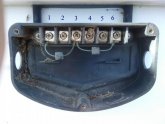
I'd appreciate some help on how to wire up an old solar panel I acquired. It's about 2' x 42" and has an array of 4 x 9 cells. The company is out of business. I've attached a picture of the box which shows 3 terminals on the negative side and 3 terminals on the positive side. I know I can check it with a meter but I'd like to know what I'm doing first. The thing that's confusing me is the installed connectors. I was hoping I could use this to run a 12v motor for a my fish pond to run an air pump.
Could someone tell me how to wire this up?
Thanks,
 

Attachments

  • Solar Pamel.jpg
    Solar Pamel.jpg
    58 KB · Views: 16
An electrician would have to test it with a volt meter as you suggested, there's no standard AFAIK to the numbers.

Even if they're out of business if you know the name/model you can probably google it. You're looking for the "j box" or "junction box" pinout. that might lead you to something like this:
B01K66959ZBP.jpg

Basically the operational principal is all the same and illustrated in a three diode panel shown below. A bypass diode is used between inner sections of the panel so that it'll still produce power even with some partial shading.

Capture.PNG

That 1 & 2 are marked "-" and 5 & 6 are marked "+" leads me to suspect that 1/2 are shorted and 2 is the negative tap. Similarly 5 is probably the positive tap. But that's just a guess, definitely measure it with you volt/ohm meter. Likewise 3 & 4 are probably shorted, and the diode from 6 was meant to go onto 4, but again just a guess.
 
Last edited:
Back
Top