diy solar

diy solar

Would this DIY surge protector work to protect MPPT charger?

fmeili1

Solar Enthusiast
Joined
Jan 19, 2022
Messages
334
Location
Arizona, Mohave County
Hi,

I'm using 8 PV strings connected to 8 individual MPPT chargers and I think about to protect the MPPT's against surges with SPD's. I'm pretty sure, it would not help against a direct lightning hit, but maybe against a lightning strike near by (all strings are correctly earthed).

Because I need 8 of them it would cost about $800 bugs (e.g. Midnight solar SPD), I think about building them by myself.

The max. MPPT input voltage is 500VDC but my max. string voltage Voc will not be over 350VDC (even with the lowest temperatures). The max. string Isc will be 14A (but usual with MPPT working <10A).

I think about the following circuit to place before each MPPT entry (inside the metal cable channel located underneath the AIO inverter/chargers):
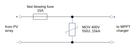
1709952722863.png
I think about placing each circuit in a separate 3D printed case to prevent hot particles flying around in case the MOV will explode in case of an surge event. I also hope that the fast blowing fuse will blow fast enough to not produce too much heat energy in the MOV in case of such an event. The case may be melt a bit in such an event but that would be ok if the heat energy will stop with the blowing fuse soon enough. I'm also not sure if the 550J MOV energy will be ok for what I want to achieve.

Also I'm not sure if such SPD's may also be useful between PV+ and ground and PV- and ground to even better protect the MPPT's (it's a non-isolated AIO)?

I ask myself if this simple circuit (cost <$10 for each unit with clamps and cases) would really help to protect anything?

Any comments welcome!
 
Last edited:
A MOV inside a transient voltage surge suppressor (TVSS) does not provide complete protection for electrical equipment. In particular, it provides no protection from sustained over-voltages that may result in damage to that equipment as well as to the protector device. Other sustained and harmful over-voltages may be lower and therefore ignored by a MOV device.

While a MOV is designed to conduct significant power for very short durations (about 8 to 20 microseconds), such as caused by lightning strikes, it typically does not have the capacity to conduct sustained energy.
 
Make sure the MOV is high enough it won't conduct at all at max Voc in cold weather.
It is only for brief transients, can carry sustained current as MarionW says.
I don't think the fuse helps.

Here's some testing I did, with links to a few parts.
I suggest getting MOV with thermistor so it doesn't burn up if it fails shorted.


You may also want to clamp PV to ground, not just +/- together.
 
Thanks for your comments.

I think I will just install the MOV's between PV+ and PV- before each MPPT but without the fuse. As you both mentioned, It's not a perfect protection because it could not withstand for longer lasting overvoltage events, but I think it's better than nothing and may help for lightning strikes near by.
The MPPT's in the AIO's are (floating) non-isolated and PV+ and PV- are not allowed to be grounded, to not damage the FET's inside. Because of that I think I should NOT place additional MOV's between PV+ and ground and PV- and ground.
I will choose a MOV voltage in the range between the highest possible Voc string voltage in coldest weather (about 350V) and the max. Voc which the MPPT's can handle (500V). So a 400V MOV looks like a good choice.
 
For that one you could also place 600V MOV from PV- to ground. You have to make sure MOV can take -600V peaks without conducting because PV- rides on top of AC waveform in this AIO inverter design. You can not ground PV- but MOV should provide around 1kV clamping. Will it save your AC side IGBTs during lightning strike? I am not sure without doing circuit simulation. But it's probably better than nothing. It's also better to place a fuse between MOV and MPPT inputs because MOV can fail short and dump current through your MPPT which is bad.
 
For that one you could also place 600V MOV from PV- to ground. You have to make sure MOV can take -600V peaks without conducting because PV- rides on top of AC waveform in this AIO inverter design. You can not ground PV- but MOV should provide around 1kV clamping. Will it save your AC side IGBTs during lightning strike? I am not sure without doing circuit simulation. But it's probably better than nothing. It's also better to place a fuse between MOV and MPPT inputs because MOV can fail short and dump current through your MPPT which is bad.
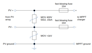
Something like this?

1710162845156.png
 
Something like this?
Yes. PV- MOV can be 600V rated, not 1kV. Usually 600V rated MOV will clamp at or above 1kV. You can also connect another 600V MOV across PV+ and ground. Make sure to mount MOVs in metal box because they could catch fire as they get old.
 
Yes. PV- MOV can be 600V rated, not 1kV. Usually 600V rated MOV will clamp at or above 1kV. You can also connect another 600V MOV across PV+ and ground. Make sure to mount MOVs in metal box because they could catch fire as they get old.
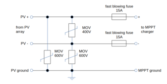
So this would be the final schema:


1710170764597.png

It's more work than I thought at the first look. So, I think about building 8 of these circuits and put them in metal cases to protect all MPPT charges at least a bit against short surges. To get rid of the metal case requirement I may consider to use MOV's with integrated thermal fuse to get rid of the metal case requirement, like @Hedges mentioned. But they would cost about 8 times more compared to standard MOV's... I need 24 of them... I'm not sure right now...
 
If MOV are $5 or $7 apiece, I'm sure you can afford them.
Compare to Midnight SPD which I think has 3 of them. (but check kA ratings, make sure it is for same protection level)

I bought a bag full. So far, have just soldered on wire pigtails, applied heatshrink to insulate, stuffed inside an SCC. Rigging up visible lights is much more work. If you put an insulated terminal over the middle leg, it would be accessible for checking with DMM.
 
Yageo 751KD20J are $0.74 in 10pc quantity on Mouser and 561KD20J are $0.65/10pc. You will also need identical MOV setup at PV array side for full protection. That's 32 x 751KD20J = $24 and 16 x 561KD20J = $10 for $34 total plus $7 shipping. I would get few extras. Place them all in one metal box together with AC side MOVs tied to same ground bar. This way lightning surge will travel around your inverters. Make sure DC power and control/data lines are also clamped to same ground bar via appropriate SPDs. Proper surge protection is complex but not expensive if you DIY your own SPDs.
 
Thanks all of you for your valuable comments! I think I will go the metal case route. Later I have to decide if using the MOV's with integrated heat protection and status LED option on top of it or using just the plain MOV's. It'll take a while until I will find time to implement it. Will update this post when finished.
 
Go with plain MOVs. They are cheap and all come with inherent audio-visual "explosive" alert when they require replacement :) No need for fuses on PV side but metal box is important for fire safety.
 
I would also add 20A 600V diodes in series with fuses for extra protection against MOV failure and subsequent current flow to ground via IGBTs but each diode would add about 7 - 10w of power loss assuming 10A PV current. Fuses may not be fast enough.
 
There are MOVs with integrated gas discharge tube for MOV leakage current protection like the Bourns GMOV line. But they top out at 415Vdc and are $2/ea. I think best solution is to use MOV in series with Thyristor called SIDACtor. See this app note for details. I wonder if this circuit can be made cheaper using discrete parts. Proper surge protection gets complicated.
 
Last edited:
I would also add 20A 600V diodes in series with fuses for extra protection against MOV failure and subsequent current flow to ground via IGBTs but each diode would add about 7 - 10w of power loss assuming 10A PV current. Fuses may not be fast enough.
The simple idea getting more and more complex ;) but I like it. I think I will develop a PCB for all 12 possible MPPT's with all components and PCB screw terminals (8 used plus 4 spare) and will order one from JLCPCB (I have good experience with JLCPCB).
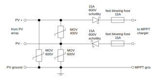
I think about using Schottky diodes to reduce the losses.

1710177957452.png
 
I like PCB idea. Just make sure diodes point in correct direction and place them on a heatsink. I am not sure if diodes will offer protection the way I imagine. I need to think about it more.
 
Back
Top