diy solar

diy solar

WTF is up with the wiring on my inverter? Deadly?

natdak

New Member
Joined
Jul 3, 2021
Messages
40
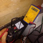
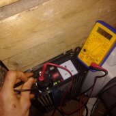
My inverter is a Photonice Universe 2000w. Ive used it for years now with all kinds of devices. But when testing to confirm the polarity it appears to be backwards!
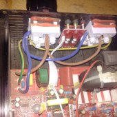
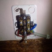
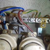
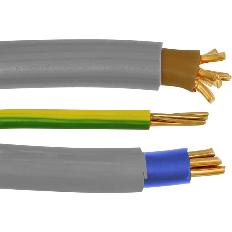
Its a brittish plug, those have the live wire on the right, neutral on the left but when I test with the voltmeter between earth the two other holes there is voltage in the left one. Implying the live wire is on the left and the neutral on the right. There is continuity between the earth and the right hole because it is neutral bonded. When I look inside everything looks how it should be. Brown (the colour for live) and blue and yellow/green. The wires are labelled live neutral and earth correctly. I have used a cooker with the inverter for a long time and touched the metal case many times which I have confirmed is electrically connected to the earth pin. I have also used a european adapter for easier insertion of the probes and confirmed that it doesnt swap the poles round. What the fuck.
 

Attachments

  • WhatsApp Image 2022-01-02 at 02.29.13.jpeg
    WhatsApp Image 2022-01-02 at 02.29.13.jpeg
    82 KB · Views: 50
  • WhatsApp Image 2022-01-02 at 02.29.12(1).jpeg
    WhatsApp Image 2022-01-02 at 02.29.12(1).jpeg
    69.5 KB · Views: 50
  • WhatsApp Image 2022-01-02 at 02.29.12.jpeg
    WhatsApp Image 2022-01-02 at 02.29.12.jpeg
    117.1 KB · Views: 50
"There is continuity between the earth and the right hole because it is neutral bonded."
What is the exact resistance reading between N (Blue wire) and GND (Green wire with Yellow stripe)? It should be < 1 Ohm if it is truly boned
Picture #3 does not show the direct connection between N and G, you can see 'Y' safety caps (Blue ceramic caps), one is between L and Gnd, another one is between N and Ground.
Also I see you are using harmonized Schuko receptacle to UK receptacle adapter?
 
The resistance starts off high then drops down to precisely 1 ohm between what my multimeter suggests neutral and ground and what everything else says is the live and ground. Could it be these safety caps that are causing the readings? Should I trust my multimeters volt readings and that the live is on the left? I am going to hook this up to an ac breaker panel.
 
Me neither, but the multimeter reads continuity between the right hole and the earth
 
The inverter is ungrounded at the minute, could that be the reason?
 
The resistance starts off high then drops down to precisely 1 ohm between what my multimeter suggests neutral and ground and what everything else says is the live and ground. Could it be these safety caps that are causing the readings? Should I trust my multimeters volt readings and that the live is on the left? I am going to hook this up to an ac breaker panel.
If the N and connected to the Gnd directly then the meter should show <1 Ohm right away the second you attach the meter probes to it, so at this point the N and G are not directly have connection between them.
 
Okay do you have an explanation for why the voltage is on the wrong side to what it should be?
 
I have now tested with a manual electrical test pencil, I thought it might clear things up. However every hole lit up the pen, including earth. I plugged in a cooker with a metal case and the case lit up the pencil when i touched it. I have touched this cookers case so many times, I even touched it after the pencil test with no shock.
 
The "test pencil" most likely shows power in close proximity. The best is a voltmeter between contact points. My inverter has an "earth ground" reference to the case. I have a voltage reading from "hot" side to case. No reading from "neutral" to case.
Do you get different results while powering a device from the ac?
 
One of the problems with modern digital Voltmeters is they have a very high input impedance of 10-15 Megohm’s
Due to this they will measure “phantom voltages” that only appear when no load is present. Some modern electrician’s voltmeters such as the Fluke 117 have a much lower input impedance of 10 k ohms. These shunt away those “stray voltages”

Electronic use voltmeters such as the Fluke 77 and 87 will read this “stray voltage” as they are designed for electronic use as opposed to line voltage use.

”Test pencils” will exhibit this very same problem.

The easy solution is to use a test lamp, say 5-10 watts to “load down” that circuit to low impedance.

Connect that incandescent (NOT LED) light bulb in parallel with your test meter to get a true reading.

I keep a 7 watt bulb on test leads in my toolbox for this exact problem.

Color codes are different here on the other side of the “pond” so I do not know what wire is hot in jolly ole england.
 
Hi Zil and Tecnodave, the pen was one of those that you put in the socket and put your finger on the top. Does that pick up power in proximity? I tried what you suggested, with something being powered, a drill battery charger and an incandescent light bulb. Still the same result, a voltage between the chassis of inverter and what is labelled neutral. Interestingly the socket on the right of the inverter doesnt pick up any voltage between the earth pin inside the socket and neutral (or live) but it does from the inverter chassis to neutral.
 
If you put your finger on top to get a reading, It is very definitely a high impedance device. Just use a small incandescent lamp, that will load down the circuit and eliminate the “stray voltage”

A closer peek at your DMM , I beleive that is a “general purpose DMM” and not an eletrician’s “low impedance voltmeter” such as Fluke’s special “electrician’s voltmeter“ which does have “low impedance”

This technology was developed by Fluke to address the problem of stray voltages found in power systems that do not appear in low power circuits.

These “low impedance” voltmeters are specifically designed for power circuits to eliminate this stray voltage that appears in any high power circuit.

There are several models that Fluke has developed that address that problem, the 117, 111, etc. they all have 3 numbers in the model name whereas the “high impedance“ models usually have 2 numbers in the model number such as 77, 78, 87, 87V, 88, etc.

I have never seen a “low impedance” voltmeter from China

AFAIK....in Britain brown is line, blue is neutral , and green with yellow stripe is ground.

You do need to have a “neutral-ground bond” somewhere in the system to estiblist the proper relationship between the neutral and ground.

If you were to string a bare wire on insulators in parallel with power lines you can harvest power from the power grid.
I know of a farmer who does just that with 2 miles of copper wire setup as a dipole antenna within 100 feet of power lines and runs his whole farm with it. He said that the voltage varies widely.

It is legal to do that here in America, Puget Power sued him in court for “stealing power” but the judge threw that out

I saw that in rural Washington (state)

That is where the stray voltages come from


DISCLAIMER.......Im a beta tester for Fluke, Im not biased towards their product but very high quality product as my training is Electrical Engineering....
 
I plugged in a lightbulb in parallel, I tested with the multoimeter, no difference in results. (the result being, steady 220v from earth to whats labelled and coloured neutral and steady 0v between earth and whats labelled and coloured live. Then i tested with this pen and no difference in results. (the result being the pen lighting up in every hole: Live neutral and earth) I know I need to bond neutral and earth and i know that I need to get it wired round the right way into the breaker panel. The question is: Which way round to connect the wires? Do I trust the voltmeters readings? or the wire colours and the labels on the circuit board?
 
I connected the inverter to the fuse box, according to the labelling inside the inverter. Thankfully I did not bond neutral and earth at the inverter because the poles were switched. This is the cable for a socket (no other sockets inbetween) brown is in the fuse and blue on neutral. The probe gave me a clean reading this time, live on the right. I opened up the socket, blue cable on the right.
 

Attachments

  • WhatsApp Image 2022-01-04 at 14.14.11(1).jpeg
    WhatsApp Image 2022-01-04 at 14.14.11(1).jpeg
    73.4 KB · Views: 4
  • WhatsApp Image 2022-01-04 at 14.14.11.jpeg
    WhatsApp Image 2022-01-04 at 14.14.11.jpeg
    71.9 KB · Views: 4
  • Like
Reactions: Zil
Fyi-while one farmer may be taking power from a line without prosecution, it is by no means accurate to say that such activity is legal in America. Nor is it safe.
 
This shows that the fused side is not live and the neutral busbar is live. (that connector goes to the neutral busbar) By this stage Im quite sure that the labelling and orientation is reversed inside the Photonice Universe 2000w IP2000 inverter.
 

Attachments

  • WhatsApp Image 2022-01-04 at 14.27.41(1).jpeg
    WhatsApp Image 2022-01-04 at 14.27.41(1).jpeg
    70.7 KB · Views: 5
  • WhatsApp Image 2022-01-04 at 14.27.41.jpeg
    WhatsApp Image 2022-01-04 at 14.27.41.jpeg
    76.5 KB · Views: 5
@Nardak

You are using a device which has a very high impedance. It will pick up stray voltage from anywhere. If you cannot obtain an electricians voltmeter use a incandescent light bulb. Connect one wire to true earth. If you have metallic plumbing in your house use that as a ground reference, this assumes that you are connected to a city? county? bourough? public water source. They are always at ground potential. Use the free probe to find what has voltage on it.

You have not stated if you have a public mains supply, that would be pertinent information.

Here in N.A. .......Black is hot........ White is not (Neutral)........ Green is ground

England............Brown is hot....(corrected)......... Blue is not (Neutral) ...(corrected).....Green is ground AFAIK....Ive never been to England

Basic electrical code everywhere....Bond Neutral to ground at one place and one place only

Try this...Ground the frame of that inverter to a known good ground, water pipe, etc.
Check the voltages now. record them use the bulb as a load and connect the meter, NOT the stray voltage detector (voltage pen)

Bond Neutral to ground , then recheck the voltages
Post results...

Something is not right with that setup. I have seen Shuko connectors, they are not legal on this side of the pond.

You are taking me into territory that puts me at risk as I cannot diagnosis the problem without my own meters in my own hands....

I am a licensed electrician here on the left edge, licensed, bonded, insured. I have a great liability here, do not want to deal with lawyers.....if you do something stupid and blame it on me, not saying that you would Any lawyer worth his salt would look up all my licenses and have a feild day with my lawyer stating that I caused whatever happened with there as a result of what you did based on my advice.

Dont worry about my english vs english, my partner is from Liverpool, I say I speak english and he speaks brit, he says he speaks english and I speak americanese......lol


<EDIT> BAD INFO CORRECTED Im still groggy, its raining and cold here on the left edge
 
Last edited:
Back
Top