You are using an out of date browser. It may not display this or other websites correctly.
You should upgrade or use an alternative browser.
You should upgrade or use an alternative browser.
Xuba Electronics: DEAL - 280AH LiFePo4 cells. Purchase & Review
- Thread starter Steve_S
- Start date
My order was returned to the logistics company because flights from China to Belgium have been suspended. They proposed shipping via UPS which would cost an additional $50 ($189 iso $139). Amy also mentioned this new shipping method would incur customs fees. I hope only the typical 21% VAT will be charged and nothing more. Delivery is expected in 5-7 days.
That sucks, probably meaning Netherlands will not be any different. Does shipping by their own shipping options means there will be no custom fees charged?
Steve_S
Offgrid Cabineer, N.E. Ontario, Canada
Mine came via UPS Express, cudtomes duties etc were all in. Now I am in Canada, I believe that is the case for USA, Canada, UK, Most of EU. This should be verified at time of purchase. I know a few folks reported they had smallish fees due upon receipt but I think that was more for handling or "extra distance" charges.
Mine came via UPS Express, cudtomes duties etc were all in. Now I am in Canada, I believe that is the case for USA, Canada, UK, Most of EU. This should be verified at time of purchase. I know a few folks reported they had smallish fees due upon receipt but I think that was more for handling or "extra distance" charges.
That was exactly what i thought..
Getting to the point where i feel confident enough to build my own lifepo4 system for my boat as well. I started a new topic with a load of questions. Hope you guys can have a look at it and help me out? I know about building small 12V systems aboard, but a larger 24V system with lifepo batteries is new to me.

 diysolarforum.com

Help with my first DIY lifepo4 system
Ok, so i am checking out loads of video's by will, reading through this forum a lot and are ready to give it a go and build my own Lifepo4 System. This is my first DIY lifepo4 system and hoping some of you could have a critical look at the design, the products i intent to buy and use and the...
Last edited:
Sgt Raven
Solar Addict
- Joined
- Feb 17, 2020
- Messages
- 1,079
You said lipo then lifepo. Those are 2 different chemistries. You have to be careful, words have meanings.Getting to the point where i feel confident enough to build my own lipo system for my boat as well. I started a new topic with a load of questions. Hope you guys can have a look at it and help me out? I know about building small 12V systems aboard, but a larger 24V system with lifepo batteries is new to me.

Help with my first DIY lifepo4 system
Ok, so i am checking out loads of video's by will, reading through this forum a lot and are ready to give it a go and build my own Lifepo4 System. This is my first DIY lifepo4 system and hoping some of you could have a critical look at the design, the products i intent to buy and use and the...diysolarforum.com
you are right ofcourse, edited it at onceYou said lipo then lifepo. Those are 2 different chemistries. You have to be careful, words have meanings.
Sgt Raven
Solar Addict
- Joined
- Feb 17, 2020
- Messages
- 1,079
You can use LFP for LiFePO4, too..you are right ofcourse, edited it at once
You can use LFP for LiFePO4, too..
That’s the beauty of standards. There are so many to choose from! ?
Rdooley79
New Member
- Joined
- Feb 25, 2020
- Messages
- 10
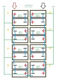
For some reason my brain is farting on the cell layout. Is this correct? Do i have the BMS leads connected to the right cell in the pair?
it looks backwards for some reason. What did I mess up?
I pulled the trigger on 16 of these 280Ah cells. Installing them in my motorhome to replace the coach batteries. It's going to be a 24v system. The cells set up for a single 24v "battery" that can be balanced with a single BMS. (Chargery BMS8T 600A) I like the display and no app for mounting in the coach next to my epever charge controller screen.
what will the actual capacity of these be? It's a lot but how much exactly set up like this at 24v? (have to admit I bought the most battery my compartment and wallet could handle not so much on Ah math....)

Last edited:
Sgt Raven
Solar Addict
- Joined
- Feb 17, 2020
- Messages
- 1,079
If you're using a single BMS, then what you want is 2P8S. Parallel the groups, first, then put the groups in series.I pulled the trigger on 16 of these 280Ah cells. Installing them in my motorhome to replace the coach batteries. It's going to be a 24v system with the cells set up in series then parallel for a single "battery" that can be balanced with a single BMS. (Chargery BMS8T 600A)
For some reason my brain is farting on the cell layout. Is this correct? Do i have the BMS leads connected to the right cell in the pair?
it looks backwards for some reason.
View attachment 8988
If I'm reading your chart right, that is what you have.
GMB
Solar Enthusiast
- Joined
- Feb 16, 2020
- Messages
- 282
16x3.2x280 = 14,336whFor some reason my brain is farting on the cell layout. Is this correct? Do i have the BMS leads connected to the right cell in the pair?
it looks backwards for some reason. What did I mess up?
I pulled the trigger on 16 of these 280Ah cells. Installing them in my motorhome to replace the coach batteries. It's going to be a 24v system. The cells set up for a single 24v "battery" that can be balanced with a single BMS. (Chargery BMS8T 600A) I like the display and no app for mounting in the coach next to my epever charge controller screen.
what will the actual capacity of these be? It's a lot but how much exactly set up like this at 24v? (have to admit I bought the most battery my compartment and wallet could handle not so much on Ah math....)
View attachment 8988
Sgt Raven
Solar Addict
- Joined
- Feb 17, 2020
- Messages
- 1,079
If I'm moving the decimal point the right way, that is also 14.34 kWh...16x3.2x280 = 14,336wh
Rdooley79
New Member
- Joined
- Feb 25, 2020
- Messages
- 10
Sgt Raven
Solar Addict
- Joined
- Feb 17, 2020
- Messages
- 1,079
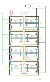
IIRC, you start with cell #1 negative, then cell #1 positive, cell #2 positive, and so on. Or is that cell #8, first negative & positive?. I can't remember which way they're numbered. Either way they're numbered, the first BMS wire goes to the negative out, then down the battery on each positive in line...Which BMS layout is correct?
Are the Positives and Negatives correct or should they be transposed?
Blue = Bus Bars
Green = BMS leads
Yellow Box / Numbering = Cell Pair
Black = each 3.2v 260Ah cell
The cell numbering was backwards in the previous post.View attachment 8991
Steve_S
Offgrid Cabineer, N.E. Ontario, Canada
Here is how my Shunbin Pack is assembled. They did it this way to ghost 3 bad cells which I now have to find replacements for so I can break the pack up into 2, 8S packs with each having it's own Chargery BMS8T. Heck of a time figuring out what was wrong but that's aside effect of this configuration... Sorry to tell you this but it is a Bad Idea ! but like my signature says....For some reason my brain is farting on the cell layout. Is this correct? Do i have the BMS leads connected to the right cell in the pair?
it looks backwards for some reason. What did I mess up?
I pulled the trigger on 16 of these 280Ah cells. Installing them in my motorhome to replace the coach batteries. It's going to be a 24v system. The cells set up for a single 24v "battery" that can be balanced with a single BMS. (Chargery BMS8T 600A) I like the display and no app for mounting in the coach next to my epever charge controller screen.
what will the actual capacity of these be? It's a lot but how much exactly set up like this at 24v? (have to admit I bought the most battery my compartment and wallet could handle not so much on Ah math....)
View attachment 8988
vk2emp
New Member
- Joined
- Mar 2, 2020
- Messages
- 101
Yep thats correct. That negative line will be on the balance lead though, its not a seperate line. There is always nCells +1 wires on a balance cable (so 4S = 5, 8S = 9, 16S =17).
Heres a quick video I made. Love the colour coded terminal covers that come with CALBS. Makes describing easy. Pointing through a veiwfinder, not so easy!!
and yes I had my phone in landscape. Youtube, WTF? you get the idea though
Heres a quick video I made. Love the colour coded terminal covers that come with CALBS. Makes describing easy. Pointing through a veiwfinder, not so easy!!
and yes I had my phone in landscape. Youtube, WTF? you get the idea though
Last edited:
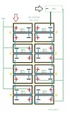
ok, here goes.... this should be correct. yes? 100% good for 2s8p layout?
The primary POS and NEG are the big arrows.
View attachment 9011
[/QUOT.
Look at Will's video.
Last edited:
vk2emp
New Member
- Joined
- Mar 2, 2020
- Messages
- 101
No! Cell 1 negative, then Cell one positive, then cell 2 positive. There will be 5 wires for a 4 cell battery, 9 wires for an 8 cell battery, and 17 wires for a 16 cell battery. Watch Wills video, his are way better quality than my quick phone shoot at 2 am 
Have you got your BMS yet?
if so look closely at the pair of the sockets on the control unit (not the display) where the balance plugs go on the bms. It TELLS you what wires go where.
Cell 1 gets 2 wires, a black and a red, then all the other cells down the chain only get one red, connected to positive. When you get to the second plug, on the Chargery's, cell 9 also gets two wires, a black and a red, other than that, its no different to a normal BMS. I have the Chargery 16S, which is the non balancing version of the 16T.
Last edited:
Before we sort out the balancing wires you need to correct the cells interconnections: the busbar between cells 2 and 3 should be on the other side, same for the one for the cells 6 and 7, and the battery terminals are on the center side of cells 1 and 8.
Similar threads
- Replies
- 4
- Views
- 278
- Replies
- 58
- Views
- 2K
- Replies
- 2
- Views
- 417


