diy solar

diy solar

YamBMS JK-BMS-CAN with new Cut-Off Charging Logic (open-source)

I personally have a Solis EH1P and a friend has a Solis RHI inverter, both work as expected with v1.17.3.

It is extremely difficult to debug your system because you are making system and configuration changes in every post you make.

To debug this properly, you'll need to:

- Reflash the firmware you are having trouble with (v1.17.3).
- Wait until you have the same lack of discharge power.
- Provide a screenshot of every single field from the ESP32 as shown in home assistant.
- Provide a picture of the inverter screen (the actual screen, not the app), including the 3 LEDs above it (power, alarm and operation).
- If the alarm led is on, provide a picture of the alarm screen, found in the advanced information. Again, not from the app, but from the inverter.

Put all of this information in one post so it's not scattered around and - potentially - we can work out what is going on.

I'm not sure why you're posting about the other JK BMS on this thread, there's a dedicated one on this forum sub-section. It's making it very difficult to follow exactly what you're doing.
@MrPablo
I think its because my name says Chaosnature - find the rhythm amongst any generated chaos :)
 
anyways - just have a look at the code - it should be something simple for you, something different and making the system not discharge,
i don't think we need a separate post for that - besides this post was created for testing of your project
 
really if there is a bug - this is for others not for me, bcos i am quite happy with sticking with the old code (works perfectly) - just letting you know
for me this is work
 
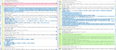
I am doing a code comparison - cant find anything obvious yet - but still looking - i think it will to do with the floating logic as this was the main issue

1710065463957.png

If you want debugging to be a different thread you can create one and tag me in then i will provide any data you ask for
 
I am doing a code comparison - cant find anything obvious yet - but still looking - i think it will to do with the floating logic as this was the main issue

View attachment 201220

If you want debugging to be a different thread you can create one and tag me in then i will provide any data you ask for
You are comparing two very different sets of logic.
Please, provide the information as requested and those of us who with experience of this code might be able to help.

If you can't do that, I don't see how any support can be offered.
 
Well remember I have MULTIPLE BMSs and MULTIPLE INVERTERS (Master-Slave configuration, so only one Inverter will talk to the CANbus anyway).

So only @Der_Hannes solution can work for me. And from what I understood he uses syssi esphome-jk-bms code to communicate with each jk-bms, not @Sleeper85. But then he implements @Sleeper85 Algorithm in his own code of course to communicate with the Inverter via CANbus .... But of course using @Sleeper85 on each JK BMS is also an option, but then I'm still needing to implement max/min/avg using @Der_Hannes code.

Unless the hack is to wire up only the weakest and most problematic BMS to the Inverter CANbus.

For now i reduced float voltage to 54.6VDC and absorbtion/equalization to 54.7VDC ... Let's see if it holds.
My code is based on v1.17.3 and is using the auto (Dic)Charge function for all configured and connected BMSs.
My code does not communicate with the BMSs directly - so you have to setup one ESP for each BMS which reports to the mqtt broker.
Based on combined values from all BMSs, the CAN-ESP controls the inverter.
So in the end both repos use syssi´s repo to communicate with the JKs

I did not start implementing v1.17.4 with the new feature - that would take a couple of days..
Before starting that, i would probably have to create a new repo for the JK-BMS-ESPs.
But so far i got no feedback on my code and i don´t know if its working for other people or not.
So I don't know if all the work would be worth it.
As I said I look forward to test it :) . I ordered a CAN adapter on Amazon and hopefully on Friday next week I'll be able to do something off a veroboard/stripboard or something like that.

I'll set the update_interval to 1s instead of 5s on the syssi esp32 though. At the top of the charge characteristic, my cell went from say 3.55V to 3.60V in less than 5 seconds ...

But I only have 2 x BMS, NO smartshunt (yet).
 
I personally have a Solis EH1P and a friend has a Solis RHI inverter, both work as expected with v1.17.3.

It is extremely difficult to debug your system because you are making system and configuration changes in every post you make.

To debug this properly, you'll need to:

- Reflash the firmware you are having trouble with (v1.17.3).
- Wait until you have the same lack of discharge power.
- Provide a screenshot of every single field from the ESP32 as shown in home assistant.
- Provide a picture of the inverter screen (the actual screen, not the app), including the 3 LEDs above it (power, alarm and operation).
- If the alarm led is on, provide a picture of the alarm screen, found in the advanced information. Again, not from the app, but from the inverter.

Put all of this information in one post so it's not scattered around and - potentially - we can work out what is going on.

I'm not sure why you're posting about the other JK BMS on this thread, there's a dedicated one on this forum sub-section. It's making it very difficult to follow exactly what you're doing.
- Reflash the firmware you are having trouble with (v1.17.3). I already did on page 14

- Wait until you have the same lack of discharge power. - i did

- Provide a screenshot of every single field from the ESP32 as shown in home assistant. - i thought the code would help here - but i can do this again -
Edit whats on the attached code should be whats on the screenshot you asked for as i did no other configuration after flashing

- Provide a picture of the inverter screen (the actual screen, not the app), including the 3 LEDs above it (power, alarm and operation). - i do not think i need to spam the forum with screenshots, there are no errors generated on the inverter screen i checked when i was doing this (other than the OVBat Code - which i understand is an interpretation of the information coming from ESP via the CAN port - at 4.1 it sees it as overvoltage even though its just 56.6 volt

- If the alarm led is on, provide a picture of the alarm screen, found in the advanced information. Again, not from the app, but from the inverter. - No Alarms

Edit:

I am reflashing to the new .17.3 again but i am not expecting to hit the issue again as the voltages has dropped from 4.1/4.0 to 3.6 due to discharge
 
Last edited:
As I said I look forward to test it :) . I ordered a CAN adapter on Amazon and hopefully on Friday next week I'll be able to do something off a veroboard/stripboard or something like that.

I'll set the update_interval to 1s instead of 5s on the syssi esp32 though. At the top of the charge characteristic, my cell went from say 3.55V to 3.60V in less than 5 seconds ...

But I only have 2 x BMS, NO smartshunt (yet).
you could use the same can module as you are using now - there is no difference i sleepers repo than mine related to that. But i understand if you want to seperate the projects in order to switch back quickly to sleepers single BMS solution
 
you could use the same can module as you are using now - there is no difference i sleepers repo than mine related to that. But i understand if you want to seperate the projects in order to switch back quickly to sleepers single BMS solution
Eh ? I do not have a CAN module right now ... I use syssi repo with the BLE connection. And Inverter is working in Voltage Mode, no BMS communication for now (hence the problems).

I only have this CAN controller module, but that would require a whole re-implementation of yours / Sleppers85 code: https://github.com/luckylinux/solar...me-can-interface-name-and-usb-can-device-name
 
ah okay i c - are your JKs already reporting to your mqtt broker?
Yes. It works fine, except when they go offline for like 6 hours every 2-3 weeks or so. Still think it's an EMC/Interference issue, but as I said, it's difficult to replicate.

Only issue, which I also suggest you to look at (we need "fast" reaction times) is to lower update_interval: 5s (default) to update_interval: 1s.

Otherwise it's too slow to react to typical Overvoltage and Overcurrent Protections on the JK BMS.
 
- Reflash the firmware you are having trouble with (v1.17.3). I already did on page 14

- Wait until you have the same lack of discharge power. - i did

- Provide a screenshot of every single field from the ESP32 as shown in home assistant. - i thought the code would help here - but i can do this again

- Provide a picture of the inverter screen (the actual screen, not the app), including the 3 LEDs above it (power, alarm and operation). - i do not think i need to spam the forum with screenshots, there are no errors generated on the inverter screen i checked when i was doing this (other than the OVBat Code - which i understand is an interpretation of the information coming from ESP via the CAN port - at 4.1 it sees it as overvoltage even though its just 56.6 volt

- If the alarm led is on, provide a picture of the alarm screen, found in the advanced information. Again, not from the app, but from the inverter. - No Alarms
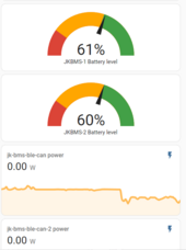
Ok, look at it from my point of view. That screenshot appears to show a subset of information from two JK-BMS ESP32s.

I don't know which one is connected to the inverter via CANbus.
I don't know what the maximum cell voltage is.
I don't know what the CAN status is.
I can't see the all of the ESP32 parameter values, which could be different from your initial YAML values.
I can't see what the protection values are as set in the BMS itself.
The error message on the inverter is important, because that can suggest the issue is upstream with inverter configuration - I'm very familiar with Solis quirks.

I'm offering unpaid support here, but if you don't provide all of the requested info... support is impossible.
Your choice.
I don't know which one is connected to the inverter via CANbus. - jk-bms-ble-can

I don't know what the maximum cell voltage is. - Operating V is 46 - 57 so max should be 4.01 but it stopped at 56.56 (my set max was 4.1.v)
I don't know what the CAN status is. - Can O.K

I can't see the all of the ESP32 parameter values, which could be different from your initial YAML values. - i am flashing back the new to grab that now

I can't see what the protection values are as set in the BMS itself. - its on the screenshot sent before - but same values are shown on the ESP board


The error message on the inverter is important because that can suggest the issue is upstream with inverter configuration - I'm very familiar with Solis quirks. - i hear you , but this cleared and inverter was one as normal
 
Yes. It works fine, except when they go offline for like 6 hours every 2-3 weeks or so. Still think it's an EMC/Interference issue, but as I said, it's difficult to replicate.

Only issue, which I also suggest you to look at (we need "fast" reaction times) is to lower update_interval: 5s (default) to update_interval: 1s.

Otherwise it's too slow to react to typical Overvoltage and Overcurrent Protections on the JK BMS.
i´m using 3s on my the JK esp code working very well. But the Current should be lowered long befor its getting critical for OVP.
I think the current logic is based on the OVPR of the BMS, lowering that value to 3.50v f.e. will then also help to prevent OVP (typical at 3.65v).
The mqtt connection is also incredibly fast, so i dont see any problems with that
 
I don't know which one is connected to the inverter via CANbus. - jk-bms-ble-can

I don't know what the maximum cell voltage is. - Operating V is 46 - 57 so max should be 4.01 but it stopped at 56.56 (my set max was 4.1.v)
I don't know what the CAN status is. - Can O.K

I can't see the all of the ESP32 parameter values, which could be different from your initial YAML values. - i am flashing back the new to grab that now

I can't see what the protection values are as set in the BMS itself. - its on the screenshot sent before - but same values are shown on the ESP board


The error message on the inverter is important because that can suggest the issue is upstream with inverter configuration - I'm very familiar with Solis quirks. - i hear you , but this cleared and inverter was one as normal
You might have an expected max cell voltage, but your assumptions are that the whole battery pack is well balanced and behaving correctly.
Seeing the actual min and max cell voltages is extremely critical - these two values control a lot of the logic in the code.

Rather than a screenshot of the combined dashboard in HA, provide a screenshot of all values associated with jk-bms-ble-can only. You can do this from the device info page.
 
i´m using 3s on my the JK esp code working very well. But the Current should be lowered long befor its getting critical for OVP.
I think the current logic is based on the OVPR of the BMS, lowering that value to 3.50v f.e. will then also help to prevent OVP (typical at 3.65v).
The mqtt connection is also incredibly fast, so i dont see any problems with that
I tend to agree. Except at the top of the charge curve in my case, one cell rises quite fast (3.55V -> 3.60V in less than 5s).
Hence my reccomendation to lower the update_interval to 1s. 3s might also be enough.

The "overhead" of the mqtt is peanuts compared to the "delay" that could be caused by update_interval on the esp32 :)
 
- Reflash the firmware you are having trouble with (v1.17.3). I already did on page 14

- Wait until you have the same lack of discharge power. - i did

- Provide a screenshot of every single field from the ESP32 as shown in home assistant. - i thought the code would help here - but i can do this again -
Edit whats on the attached code should be whats on the screenshot you asked for as i did no other configuration after flashing

- Provide a picture of the inverter screen (the actual screen, not the app), including the 3 LEDs above it (power, alarm and operation). - i do not think i need to spam the forum with screenshots, there are no errors generated on the inverter screen i checked when i was doing this (other than the OVBat Code - which i understand is an interpretation of the information coming from ESP via the CAN port - at 4.1 it sees it as overvoltage even though its just 56.6 volt

- If the alarm led is on, provide a picture of the alarm screen, found in the advanced information. Again, not from the app, but from the inverter. - No Alarms

Edit:

I am reflashing to the new .17.3 again but i am not expecting to hit the issue again as the voltages has dropped from 4.1/4.0 to 3.6 due to discharge
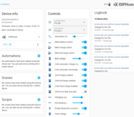
O.k flash complete and i was wrong - the issue still there even with the voltage drop - this version once worked , so i am now supecting i must have touched a config that is making it exibit this behaviour
1710068009890.png

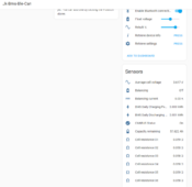
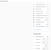
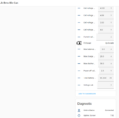
Here is the Jk talking to the CAN full ESP screenshot as requested

1710068102396.png
1710068159079.png
1710068192656.png
1710068228072.png
1710068266257.png

i noticed the float and other para is not showing so here they are
Absorption offset - 0.05
Bulk charge -57.1
charge/discharge current - 30
float - 55.3
rebulk 53.7
 
You might have an expected max cell voltage, but your assumptions are that the whole battery pack is well balanced and behaving correctly.
Seeing the actual min and max cell voltages is extremely critical - these two values control a lot of the logic in the code.

Rather than a screenshot of the combined dashboard in HA, provide a screenshot of all values associated with jk-bms-ble-can only. You can do this from the device info page.
ys all balanced - screenshot provided
 
I tend to agree. Except at the top of the charge curve in my case, one cell rises quite fast (3.55V -> 3.60V in less than 5s).
Hence my reccomendation to lower the update_interval to 1s. 3s might also be enough.

The "overhead" of the mqtt is peanuts compared to the "delay" that could be caused by update_interval on the esp32 :)
you probably can set it to 1s - my code only sends data if the value has changed to prevent unnessecary traffic on the mqtt side
should be fine
 
O.k flash complete and i was wrong - the issue still there even with the voltage drop - this version once worked , so i am now supecting i must have touched a config that is making it exibit this behaviour
View attachment 201228

Here is the Jk talking to the CAN full ESP screenshot as requested

View attachment 201229
View attachment 201230
View attachment 201231
View attachment 201232
View attachment 201233

i noticed the float and other para is not showing so here they are
Absorption offset - 0.05
Bulk charge -57.1
charge/discharge current - 30
float - 55.3
rebulk 53.7
There should be some additional fields in the diagnostic section as well.
 

diy solar

diy solar
Back
Top