• Have you tried out dark mode?! Scroll to the bottom of any page to find a sun or moon icon to turn dark mode on or off!

diy solar

diy solar

ZKETECH EBC-A40L 40 amps 10ga (3.2mm) wire too small? and RC plugs for it?

gotbeans

Solar Cooking Beans
Joined
May 11, 2023
Messages
1,332
Location
co/ar
This device is meant to test/charge batteries which means it's running like 10 hours or even more at a time.
It is rated for 40 amps but it has a 10 gauge wire. (3.2mm)
It gets warm and I've been running it at 34 amps.. but not hot.. warm.
I know all the ratings all over the internet say 30amps max for 10ga which is why I wonder.
Looking up metric ratings (for that size of wire in mm) they seem to recommend even lower amperage..
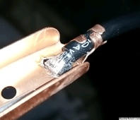
The connections are going to support 40amp? (picture 1)

I know someone's going to come in here and say "it doesn't melt itself until 50amps!" or something but just curious what people think about the 40 amps

Also they must exist, what are the plugs for an RC car for 40 amps or some other type of plugs so I can plug different connectors into the end of the wire?
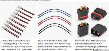
In picture 2 you can see some but only 1 is rated at 40 amps for a split second then it's continuous current is 20 amps
 

Attachments

  • 1702069680832.png
    1702069680832.png
    1,005.1 KB · Views: 12
  • 1702069748799.png
    1702069748799.png
    242.5 KB · Views: 12
Hi Gotbeans
Did hear mention of the fact that the wires are a bit skimpy...if they are easy to replace I’d go for it... can’t help you with the RC thing.. good luck..?
 
Hi Gotbeans
Did hear mention of the fact that the wires are a bit skimpy...if they are easy to replace I’d go for it... can’t help you with the RC thing.. good luck..?
so far not too hot except the solder joint gets super hot I'm thinking I'll just put a massive glob of solder on it for now
thanks though.. Hopefully someone knows some plugs to switch out the heads to the leads
 
found some quick connectors

I'm surprised nobody looks at this.
@timselectric maybe you feel like answering.. This uses 10 gauge wire for 40 amps continuous current. This goes against typical charts. Are all of these only based on 120v ac?
I see silicone 200c (temperature) wire can do even up to 60 amps or whatever at 10 gauge..
Should I follow this chart for batteries too? If not, why is it followed for these types of charging devices that are left on for days at a time at max lol
batteries don't even run as heavily as these chargers do
 
i jsut finished capacity testing my calbs and ran the same tester at 40 amps for charge and discharge. roughly 10 hours per cell. cables got warm, but not so hot that the silicone jackets were in any danger. YMMV
Yea I've had it on non stop since this thread was made, almost a month now. Testing many batteries.
I'm sure the solder joints are different in every machine though but doesn't really matter there
 
Yea I've had it on non stop since this thread was made, almost a month now. Testing many batteries.
I'm sure the solder joints are different in every machine though but doesn't really matter there
thats about how long mine ran though there were periods when it was idling as i was asleep and did not wake up to swap cells.
 
I'd say teach the kids to switch the battery.. but they're gonna short it o_O
2nd family, 56 with a 12, and 13 year old daughters. so yeah I am trying to build the system so that its KISS and the kids can keep the cabin when i pass on. redundancies on everything and the battereis far enough away from the cabin that if something does happen the cabin will be safe. but I would guess in honesty by the time they get older they will have no interest in it as all the younger ones want is the newest playstation DS or other handheld mind melter.
 
Yea if they don't have interest by ~16 years old they'll likely never have interest.
Everyone I know whom has interest in electronics or general taking stuff apart had it when they were like 6 or even younger lol
 
@gotbeans Did you ever build larger diameter test leads for the a40? It seems silicone jacketed wires can have a higher amperage rating than something like a normal insulated thhn/thwn. If I understand correctly, it's not that the copper can handle more current, it's just the insulation doesn't burn off as early. Anyhow, resistance is warmth and it bothers me that the leads get warm under testing. Those test leads feel super supple which makes me wonder if they are cca.

What type of connector is it that goes into the a40L? Have you found a source? What's the largest size wire that will fit?

Have you tried to remove the alligator clamps and replaced them with ring terminals?
Ring terminals were the first thing I did but used the same wire mine was real copper not CCA or anything else
 
@gotbeans Did you ever build larger diameter test leads for the a40? It seems silicone jacketed wires can have a higher amperage rating than something like a normal insulated thhn/thwn. If I understand correctly, it's not that the copper can handle more current, it's just the insulation doesn't burn off as early. Anyhow, resistance is warmth and it bothers me that the leads get warm under testing. Those test leads feel super supple which makes me wonder if they are cca.

What type of connector is it that goes into the a40L? Have you found a source? What's the largest size wire that will fit?

Have you tried to remove the alligator clamps and replaced them with ring terminals?
yea they can, even thhn/thwn is pretty high vs some other wires too.
I fixed the connection points to the terminals and most of the heat went away. I ended up cutting the wire and soldering a splitter on both ends.. one to the clamp thing and one to a ring terminal / wire lug thing that I can screw down to the battery which gave a better connection, that greatly reduced heat.
Most I'd run through the clamp things on the smaller badly connected terminals is like 30amps.. but with the ring connector 40 is not getting "hot" just warm which to touch means it isn't hot at all since our skin burns pretty low temp

not sure what their name is, it's just some wire clamp thing like on a battery jumper cables?
As far as the size that it can handle it should be like 8 gauge if you stripped it all back in those clamp things so there's no insulation there. Doesn't seem necessary though.
the solder connections on MINE were bad which caused the initial heat I was experiencing. I did it better and it reduced it noticeably but then the different connector altogether was way better.

and to be clear when we're discussing ring terminals I am talking about (random pic not the exact one I used so ignore the numbers on it)
1728330224779.png
 

diy solar

diy solar
Back
Top