


You are using an out of date browser. It may not display this or other websites correctly.
You should upgrade or use an alternative browser.
You should upgrade or use an alternative browser.
The Electrodacus SBMS thread (SBMS0, DSSR50, etc)
- Thread starter Dzl
- Start date
childcarepro
New Member
- Joined
- Jul 5, 2020
- Messages
- 101
Your 60-cell panel should contain bypass diodes. With these diodes a series configuration does better in shade than parallel.
Shut up! You're blowing my mind right now. I can have my cake AND eat it too? Best of both worlds? I don't have the panels yet, but I will have to do that. Dzl mentioned bypass diodes, but he didn't elaborate much.
I checked my Newpowa 200W 24V (20V) panels, it lists under features: "Pre installed bypass diodes inside junction box that minimize power drops caused by shading."
AltE store's FAQ says:
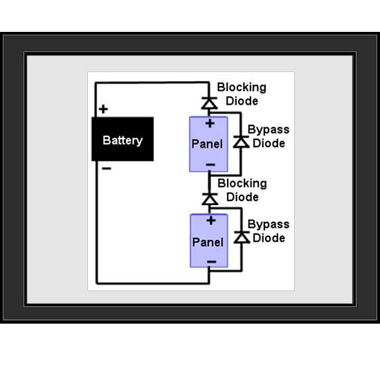
Most solar panels have bypass diodes built in these days, so you typically won’t have to worry about that anymore. However, if you have multiple solar panels wired together in series, and you consistently have shading on one or more of the solar panels, wiring a bypass diode in parallel across the shaded panel can prevent the current from being forced back through the shaded panel and cause it to heat and lose power. So, it acts the same as the internal bypass diodes, but bypasses the entire panel instead of the individual cells.
With an RV, there won't be consistency in which panels will be shaded, as in a residential installation, so would this external bypass diode be a thing for me to consider? I'm planning (now) on wiring my 6 panels as 2S3P, trusting the bypass diodes to prevent shading from killing the voltage on a whole series pair?
Last edited:
Shut up! You're blowing my mind right now. I can have my cake AND eat it too? Best of both worlds? I don't have the panels yet, but I will have to do that. Dzl mentioned bypass diodes, but he didn't elaborate much. I'll look into that.
There is a link I posted in one of my responses, it has some info, I'll try to dig it up, hold on.
Basically they give current a path around the shaded cell(s). A small panel is usually cut in half, A large panel is cut in 3rds or 6ths.
Last edited:
PV Module Bypass Diodes – What are they and what do they do? - SunWize | Power Independence
Leading-Edge Autonomous Power Solutions
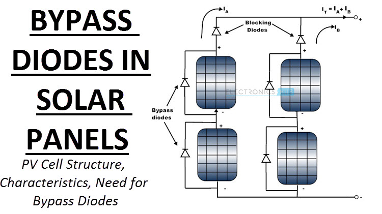
Bypass Diodes in Solar Panels
Basic tutorial about Bypass Diodes in Solar Panels, Construction of Photovoltaic Cells, characteristics of PV Array, Maximum Power Point.
 www.electronicshub.org
I have an SBMS0, and I like the available control lines and settings. Also like the ability to connect via WiFi. It's limited, but being improved by some of the users with Dacian's support, it is an open source platform. I haven't tracked that work lately as I'm on other parts of my van project right now but I plan to pick up that code.
I'm not sold on DSSR vs MPPT. Although I did buy a DSSR to play with it because it is so cheap. Once I get my van running I plan to run 2 panels on DSSR and 2 on MPPT and do a compare over time, just for my curiosity. No data at present though.
I have also had a few discussions with Dacian, via email and in his forum. I will say that he is extremely responsive and accessible. Including when I found a defect in the Lock functions. He turned around a fix and a new FW release in a couple days. I do appreciate his responsiveness. As to whether he hypes... I think @Dzl got it right:
He is a really smart guy but he gets religous about his approach, and he has tunnel vision on use cases. For example he seems fundamentally incapable of grasping an RV use case. I don't care what alternator efficiency is nor what it costs in diesel fuel to charge my battery bank. I just want to charge it. You will never get through to him on that or on other topics out of his focus, so best just to move on. Evaluate the SBMS0 and DSSR and if it works for you, great, use it.While I think there are blindspots in his argument, and I think he tends to get laser focused on one particular use-case or factor and not fully acknowledge or consider alternative use-cases/design goals, I definitely don't feel that he is acting in bad faith or trying to hype his product. He is a very disarming and straightforward guy, and strikes me as very honest, even when I disagree with him or feel he is overlooking something.
Well I disagree with you on BMS purpose, but that aside--this is incorrect. There's no reason you can't add disconnects in addition to controls. There are sufficient control lines and you can use separate settings (the OV Lock and UV Lock) to drive the disconnect devices of your choice. That's one of the things I like about this BMS vs. others.BMS main purpose isn't to be a controller, it's to be a safety device when the other things crap out. If it can only control the thing that crapped out and can't cut power itself then it's pretty much useless. For example: mosfets in your SCC have short-circuited, battery is in over voltage, what this BMS will do? nothing; it'll try to turn the SCC off but it can't so the battery will continue charging until the cells are destroyed.
Hey @Cal, long time no speak. What are you looking for on the SBMS0? As @LB3 said, if you're interested in the SBMS0 then join his forum, he will respond as will others there.I actually got involved in this thread/discussion because I may purchase one of his units. I'm looking for info. No hype please!
childcarepro
New Member
- Joined
- Jul 5, 2020
- Messages
- 101
Thanks @Cal and @Dzl for your help. It seems the partial shading videos I was watching is on old bypass-less panels? Cause their whole series production was KILLED by partial shading of a few cells. My panels have bypass diodes and should work just fine in series.
@Cal, I admire your economy of words, but how would panels with bypass diodes work better than in parallel? At most it should work the same, no?
@Cal, I admire your economy of words, but how would panels with bypass diodes work better than in parallel? At most it should work the same, no?
Well I disagree with you on BMS purpose, but that aside--this is incorrect. There's no reason you can't add disconnects in addition to controls. There are sufficient control lines and you can use separate settings (the OV Lock and UV Lock) to drive the disconnect devices of your choice. That's one of the things I like about this BMS vs. others.
I didn't say the BMS can't control other things, but just that it's not its main purpose, you can totally have other things in addition to that
")
You're correct, I didn't thought about that. However this is not the primary use case intented, else the disconnect would be sold with the BMS.
@Cal, I admire your economy of words, but how would panels with bypass diodes work better than in parallel? At most it should work the same, no?
In the interest of economy of words, the short answer is no. They do not work the same.
Some basics... In a parallel string, panel voltage is the dominate factor, while panel current doesn't matter. In a series string these relationships are reversed. In series, current is king. This means every panel in the series string has the exact same current. Panel voltage is a lesser factor.
So now we got some panels (36 cells in series), containing 3 bypass diodes. The maximum power point of the panel is 18V. Each of the 3 diode sections produce 6V. If one of the sections is shaded, and the bypass diode conducts, then the panel outputs 12V. In a two panel series string the total voltage reduces from 36V to 30V. The current remains the save, let's say 5A. Total power reduces from 180W to 150W.
In the parallel configuration one panel is at 18V and the other at 12V. The 12V panel becomes a non-factor as battery voltage is above 12V. Total power reduces from 180W to 90W.
You're right that the safety disconnect capability is not Dacian's primary targeted use case. In fact he argued with me about the need for it while simultaneously jumping on fixing a defect I found in it. While he doesn't value it that much, it is listed as a supported feature and he ensured it works. He feels that cutting power (actual power interrupt, not just a remote control line) to any chargers is sufficient, beyond that is corner cases.I didn't say the BMS can't control other things, but just that it's not its main purpose, you can totally have other things in addition to that
You're correct, I didn't thought about that. However this is not the primary use case intented, else the disconnect would be sold with the BMS.
And I do think that shorted FETs in a charger are a corner case. If someone is worried about shorted FETs then they wouldn't use any of the BMSs that come with FET switches built in, use only relays. Of course mechanical relays have their own failure modes. I worked in test equipment design and we got rid of mechanical switches in attenuators decades ago due to reliability issues.
Lots of views on purpose of a BMS, my view is its purpose is to manage the health of the battery. And I prefer to control charging based on state of the battery including individual cell voltages, not just pack voltage. Actually it was @Cal who first argued that point with me and I came to agree. The SBMS0 enables me to do that, and Victron equipment lets me control actual power switch for charger and inverter separately. They work very well together.
childcarepro
New Member
- Joined
- Jul 5, 2020
- Messages
- 101
Some basics... In a parallel string, panel voltage is the dominate factor, while panel current doesn't matter. In a series string these relationships are reversed. In series, current is king. This means every panel in the series string has the exact same current. Panel voltage is a lesser factor.
So now we got some panels (36 cells in series), containing 3 bypass diodes. The maximum power point of the panel is 18V. Each of the 3 diode sections produce 6V. If one of the sections is shaded, and the bypass diode conducts, then the panel outputs 12V. In a two panel series string the total voltage reduces from 36V to 30V. The current remains the save, let's say 5A. Total power reduces from 180W to 150W.
In the parallel configuration one panel is at 18V and the other at 12V. The 12V panel becomes a non-factor as battery voltage is above 12V. Total power reduces from 180W to 90W.
Awesome! Thank you for speaking up and disabusing me of my OLD, pre-bypass diode knowledge.
In my case I have 60 cells in series w/ 3 bypass diodes, so the wattage numbers may change, but the ratios are still the same. I am definitely sold! Thanks again!
Hey Airtime. Yeah, long time. Other than sub-par current measurements, I'm happy with Chargery. I would like to know if SBMS0 does a better job in AH counting. Chargery uses a 12-bit A/D which should provide close to adequate current resolution, but it shuts down current measurements in the +/- 1.0A region. My RV has a 0.7A quiescent load current. That's my load at night. Chargery registers 0A. That means in a 24 hour time span, Chargery misses about 0.7A * 10 hours = 7 AH. In a short time period the SOC display shows greater than 90% when in reality the battery might be at 50%. SOC is important to me as that's my gauge to how much shade is acceptable. This summer I camped in a lot of shade since SOC always showed greater than 90%. That was a mistake!
What's SBMS0 current resolution when using a 300A load shunt? It's already strange that it requires 2 shunts. Do you know if SOC is accurate? Usually these meters have a reset to 100% when battery gets fully charged. How accurate is SOC when battery doesn't get fully charged for a week? Have you noticed any current measurement stability issues when measuring small quiescent currents? I'm looking into the possibility of building my own BMS. I built a current monitor/counter which currently has a thermal offset error. The error is coming from the instrumentation amp. Thermal offset error might be in the +/- 0.5A region. That blows my quiescent current measurement out of the water. Is that why Charger doesn't measure current less than 1A?
Regarding DSSR: is that a simple FET on/off switch? That means the fet switch connects solar to the battery. Once any cell reaches max voltage the fet opens and charging is terminated. That's quite risky isn't it? The system isn't fault tolerant. A fault will overvoltage the battery. You may add an additional relay (controlled by OV Lock) between panel and DSSR. But that helps only if the DSSR fails. If something within SBMS0 fails then the battery will still overvoltage.
childcarepro
New Member
- Joined
- Jul 5, 2020
- Messages
- 101
My Winnebago Via has a Zamp Solar 3 port combiner box on the roof, which I learned contains a 12V 40A breaker (Bussmann 121A40-A2P). It's apparently rated for 12V±2, though no one has actually reported failures at the 18V most RV solar panels run at.
 www.adventurousway.com
So with 40V nominal (68V Vmp) at 2S3P, or 60V if I do 3S2P (102V Vmp), I gotta pull that part.
Either way I need to open it up and reverse the wiring, as Zamp uses SAE connectors w/ reverse polarity.
Unsafe Zamp Solar Combiner Box
Many RVs nowadays are coming with rooftop solar pre-installed, or at least pre-wired for you to add solar panels later. If you have solar on your roof or are considering installing solar, you should DEFINITELY read this...
www.adventurousway.com
So with 40V nominal (68V Vmp) at 2S3P, or 60V if I do 3S2P (102V Vmp), I gotta pull that part.
Either way I need to open it up and reverse the wiring, as Zamp uses SAE connectors w/ reverse polarity.
Don't believe that's an issue. Are there 3 breakers or just one? Each of the 3 panel connections should have its own breaker. The breaker is sized just greater than the panel's short circuit current. That's a requirement. There's no requirement for a single breaker. I would chuck the breaker.
In any event, the issue the guy raises is, in my opinion, not a problem at all. The breaker bursting problem is related to the energy it is consuming.
18V * 30A = 540W
However, current at Voc is zero. Current greater than Vmp decreases. You'll never see high currents in that region. The breaker will never see high currents when subjected to higher voltages.
Sorry long reply but you asked a lot of questionsHey Airtime. Yeah, long time. Other than sub-par current measurements, I'm happy with Chargery. I would like to know if SBMS0 does a better job in AH counting. Chargery uses a 12-bit A/D which should provide close to adequate current resolution, but it shuts down current measurements in the +/- 1.0A region. My RV has a 0.7A quiescent load current. That's my load at night. Chargery registers 0A. That means in a 24 hour time span, Chargery misses about 0.7A * 10 hours = 7 AH. In a short time period the SOC display shows greater than 90% when in reality the battery might be at 50%. SOC is important to me as that's my gauge to how much shade is acceptable. This summer I camped in a lot of shade since SOC always showed greater than 90%. That was a mistake!
What's SBMS0 current resolution when using a 300A load shunt? It's already strange that it requires 2 shunts. Do you know if SOC is accurate? Usually these meters have a reset to 100% when battery gets fully charged. How accurate is SOC when battery doesn't get fully charged for a week? Have you noticed any current measurement stability issues when measuring small quiescent currents? I'm looking into the possibility of building my own BMS. I built a current monitor/counter which currently has a thermal offset error. The error is coming from the instrumentation amp. Thermal offset error might be in the +/- 0.5A region. That blows my quiescent current measurement out of the water. Is that why Charger doesn't measure current less than 1A?
Regarding DSSR: is that a simple FET on/off switch? That means the fet switch connects solar to the battery. Once any cell reaches max voltage the fet opens and charging is terminated. That's quite risky isn't it? The system isn't fault tolerant. A fault will overvoltage the battery. You may add an additional relay (controlled by OV Lock) between panel and DSSR. But that helps only if the DSSR fails. If something within SBMS0 fails then the battery will still overvoltage.
Yes it does better than the Chargery on current but that's a low bar. I haven't taken data in any rigorous fashion yet... Got my system up and running on my bench and then mostly left it running with fridge connected while I did other things like pick up Arduino so I could do some remote monitoring and then Solidworks so I could design and order my 80/20 structure. I'll eventually characterize it more, but for now I'm satisfied with it.
When you power up the SBMS0 you have to ensure that it's fully disconnected from battery and all charging sources and loads. It calibrates zero current at bootup. And it also does reset 99% SOC (not 100%) at end of charge.
His hardware is open source and he publishes schematics. They can be a bit hard to follow, personally I would organize it better but most of the info is there. He uses the STM32F373 MCU which has three 16 bit sigma delta ADCs and one fast 12 bit ADC. So it has resolution. That said, the current sense amp is an LMP8481 with input offset drift of 6uV/C which can can be a factor over a wide temp range and vs. 75mV input from shunt. The displayed current and voltage measurements have more resolution but are still a bit noisier than I would like. Much much better than Chargery however. I recall some discussion on resolution and small current errors on the forum, I have not yet dug through that might be worth reading.
I did one non-scientific experiment where I booted for a fresh zero current calibration, hooked up my fridge (Isotherm 115, uses about 0.45A average at 24V), fully charged it, and then let it run without charging. It lasted about 3 weeks. It was in a shop with no climate control, tempuratures inside varied maybe 20-30F over that period. When it finally fell off the lower knee, the SOC still read 22%. LVD worked as expected which is good because I wasn't there to observe!!
I have a 280Ah 24V pack so that works out to about a 0.1A error in measuring 0.5A over that 3 week period, could be shunt gain error or offset calibration error or some temperature-driven offset errors, or more likely a mix. I'd like a bit better, but I'd be pretty comfortable going a week between full charges with SOC reset. Again this is one unscientific datapoint, I have not dug into this in any depth just yet.
Two shunts--that's just because he's really into logging and understanding solar input in his house. The separate shunt lets him monitor solar charging separately and also with higher resolution since you can use a lower current shunt for measuring solar.
DSSR--yes it is a simple FET switch. Yes if it shorts then it would overcharge the pack unless you also had an additional safety disconnect switch driven by OV Lock--which the SBMS0 supports. You can set wider cell limits for OV Lock than for normal OVD for charge termination. But I think the risk of an appropriately sized, derated, and protected FET switch shorting out is pretty small. That said I haven't dug into Dacian's FET switch design yet. I actually did buy some NO Tyco 500A relays to use for disconnects but haven't yet used them.
If the BMS itself fails--I don't know how you handle that in general, other than by having a separate redundant BMS driving the disconnects. For example if the BMS FW locked up and all control lines remained in last state, then nether OVD nor OV Lock would trip and so no switches would open.
I might actually hook up the Arduino to drive the emergency relay disconnects with an OR connection in the relay control. I'm already using it to monitor pack voltage separately. Could act as a very crude redundant BMS. Could also trigger it remotely if I wanted.
What's SBMS0 current resolution when using a 300A load shunt? It's already strange that it requires 2 shunts. Do you know if SOC is accurate?
Two shunts--that's just because he's really into logging and understanding solar input in his house. The separate shunt lets him monitor solar charging separately and also with higher resolution since you can use a lower current shunt for measuring solar.
Adding to this, it is my understanding that the second shunt is entirely optional. But the dual shunt setup is one of the distinguishing features of the SBMS0, and what enables energy in, energy out, and net in/out to be tracked (as opposed to a single shunt setup where you see net in/out). If this functionality is not important, I believe you can just use a single shunt.
You're right that the safety disconnect capability is not Dacian's primary targeted use case. In fact he argued with me about the need for it while simultaneously jumping on fixing a defect I found in it. While he doesn't value it that much, it is listed as a supported feature and he ensured it works. He feels that cutting power (actual power interrupt, not just a remote control line) to any chargers is sufficient, beyond that is corner cases.
Did this conversation occur on Dacian's google group? It piques my interest, I would like to read up on it if you have a link. By safety disconnect capability are you referring to essentially a second line of defense with a slightly wider bandwidth (also controlled by the BMS) that triggers a relay or something similar that cuts all charging or discharging (or both)?
My Winnebago Via has a Zamp Solar 3 port combiner box on the roof, which I learned contains a 12V 40A breaker (Bussmann 121A40-A2P). It's apparently rated for 12V±2, though no one has actually reported failures at the 18V most RV solar panels run at.
This doesn't sound right. Actual 12v panels are non-existant or virtually non-existant. A PV Array component that can't handle more than 12v+/-2v (lower voltage than the lowest voltage common solar panels) seems negligent and potentially dangerous.
And I do think that shorted FETs in a charger are a corner case. If someone is worried about shorted FETs then they wouldn't use any of the BMSs that come with FET switches built in, use only relays. Of course mechanical relays have their own failure modes. I worked in test equipment design and we got rid of mechanical switches in attenuators decades ago due to reliability issues.
Well shorting is the main failure mode for mosfets so it would not be very surprising if it happens to someone one day. Yep, but usually BMS have more robust mosfets and they are more over spec'd but they can fail too of course. But to have both fail at the same time... you'll be really unlucky, better not go out of your bed at all that day
but that's also why I would never not put a fuse on the battery, even with the best of the best BMS Lots of views on purpose of a BMS, my view is its purpose is to manage the health of the battery. And I prefer to control charging based on state of the battery including individual cell voltages, not just pack voltage. Actually it was @Cal who first argued that point with me and I came to agree. The SBMS0 enables me to do that, and Victron equipment lets me control actual power switch for charger and inverter separately. They work very well together.
I have no problem with that if that's what you want
Hey Airtime. Yeah, long time. Other than sub-par current measurements, I'm happy with Chargery. I would like to know if SBMS0 does a better job in AH counting. Chargery uses a 12-bit A/D which should provide close to adequate current resolution, but it shuts down current measurements in the +/- 1.0A region. My RV has a 0.7A quiescent load current. That's my load at night. Chargery registers 0A. That means in a 24 hour time span, Chargery misses about 0.7A * 10 hours = 7 AH. In a short time period the SOC display shows greater than 90% when in reality the battery might be at 50%. SOC is important to me as that's my gauge to how much shade is acceptable. This summer I camped in a lot of shade since SOC always showed greater than 90%. That was a mistake!
You should ask Dacian as I know he does something similar (forcing the value to 0 under a certain threshold) but IIRC he lowered the threshold. Well, ask him, you'll now for sure
It's already strange that it requires 2 shunts.
Well he wants to be able to differenciate solar current and load current so that's the only way. What's strange is that he does one shunt for the total current and one for the solar instead of one for the loads and one for the solar. But that's no big deal, just doing a substraction instead of an addition in software.
That blows my quiescent current measurement out of the water. Is that why Charger doesn't measure current less than 1A?
Probably something similar yep. Accuracy isn't stellar so the easy fix is to clamp the value to zero in software to avoid ghost values near zero.
Regarding DSSR: is that a simple FET on/off switch? That means the fet switch connects solar to the battery. Once any cell reaches max voltage the fet opens and charging is terminated.
IIRC it's basically a SSR with two mosfets back to back to avoid the body diode problem.
That's quite risky isn't it? The system isn't fault tolerant. A fault will overvoltage the battery. You may add an additional relay (controlled by OV Lock) between panel and DSSR. But that helps only if the DSSR fails. If something within SBMS0 fails then the battery will still overvoltage.
Yep, especially when you have several of them in parallel, one shorting is enough to have problems. That's what bugs me the most about this BMS, it doesn't protect the battery against basic faults. And for the protections it actually has there's no redundancy.
His hardware is open source and he publishes schematics. They can be a bit hard to follow, personally I would organize it better but most of the info is there. He uses the STM32F373 MCU which has three 16 bit sigma delta ADCs and one fast 12 bit ADC. So it has resolution.
What's the accuracy of the Vref tho? because I bet the internal one isn't really accurate and will drift with the temp.
If the BMS itself fails--I don't know how you handle that in general, other than by having a separate redundant BMS driving the disconnects. For example if the BMS FW locked up and all control lines remained in last state, then nether OVD nor OV Lock would trip and so no switches would open.
Well in general you have a SCC and a BMS so if the first fails the second will save the day. Here the BMS is actually the SCC too and has no redundant disconnect (well you can add one yourself as you said earlier, but it's still the same non-redundant brain so not really redundant actually).
Yes, in the google group. Here's a link or just search on "EXTIO defect"Did this conversation occur on Dacian's google group? It piques my interest, I would like to read up on it if you have a link. By safety disconnect capability are you referring to essentially a second line of defense with a slightly wider bandwidth (also controlled by the BMS) that triggers a relay or something similar that cuts all charging or discharging (or both)?
And yes that is what I mean by safety disconnect.
I did intentionally say resolution and not accuracyWhat's the accuracy of the Vref tho? because I bet the internal one isn't really accurate and will drift with the temp.
. Good point on Vref, another temp drift mechanism along with current sense amp input offset voltage.
Meant to comment on that as well. Keep in mind that the DSSR is optional. You are free to use an MPPT controller with the SBMS0 if you want, whether for performance or for a redundant and independent disabling of solar charging.Yep, especially when you have several of them in parallel, one shorting is enough to have problems. That's what bugs me the most about this BMS, it doesn't protect the battery against basic faults. And for the protections it actually has there's no redundancy.
...
Well in general you have a SCC and a BMS so if the first fails the second will save the day. Here the BMS is actually the SCC too and has no redundant disconnect (well you can add one yourself as you said earlier, but it's still the same non-redundant brain so not really redundant actually).
I did intentionally say resolution and not accuracy
Good point on Vref, another temp drift mechanism along with current sense amp input offset voltage.
Yep I know, but that's why I was more interested by the accuracy
So I checked quickly and it's a 1.23 V reference with 100 ppm/°C so that's very good actually, that's 0.1 % for 10 °C.
Most of the error should come from the analog frontend.
Meant to comment on that as well. Keep in mind that the DSSR is optional. You are free to use an MPPT controller with the SBMS0 if you want, whether for performance or for a redundant and independent disabling of solar charging.
Yep of course, but realistically 95 % of people using the SBMS will use the DSSRs.
BTW I checked on the pictures (too lazy to find the schematics...) and the DSSRs are apparently 2x two mosfets back to back @Cal
Similar threads
- Replies
- 78
- Views
- 6K
- Replies
- 14
- Views
- 2K