diy solar

diy solar

Chargery BMS, DCC (Solid State Contactor) thread.

Well, is it relative or not. My system is basically designed for 200A Draw but everything is setup for 300A. 300A DCC, 300A Breakers, my Main Breaker in the Midnite E-Panel is 250A. I'm running a 24V system. On the rare occasion I "may" hit 200A pull if I decide to use heavy tools but compressor, mig only see the generator for power. I am power frugal and have all LED lights & high efficiency stuff.

Normal running with Computer on the fridge running (4A), and a couple of lights, I'm pulling 10A from the battery.
Coffee Maker draws 50A for 6 minutes while it brews.
Panasonic 1200W Inverter Nuke pulls 90A at full power
Radiant Heating System uses 4A when it runs (2 hrs per 24hr period @ -20C exterior temp) {High Efficiency Build makes the difference}
Deep Well Pump is only 1100W @ 120VAC and does not run much.
 
The only way for a mosfet to fail shorted is by over current (most likely you short the battery cables) and I will always recommend a fuse in addition to the BMS; it will take care of that problem in case it happens ;)
But mosfets/ssr fail at their highest instantaneous current, which is quite easy to hit even with fastblow fuses. And while it's possible to weld a contactor close its extremely unlikely, the main problem w/ mechanical contactors are back emf and coil power usage/heat buildup both of which are fixable. The usual failure mode of contactors is carbon buildup at the contacts, followed by pitting.

I'm sorry Steve but the more I think about it the less I like the SSR idea, the small but real possibility of an invisible failure in such a critical junction with a Chinese produced SSR of unknown parentage scares me just a little too much in a system that may be in place for decades.

Edit: Maybe it's just me, I work in a field where failures cause really BAD THINGS to happen unless they 'fail safe' my risk tolerance is probably different than most.
 
I'm confident enough with the DCC's that I'm putting 8 TE/Kilovac EVE200ANA up for sale at $30 USD + S&H. Keeping my pair of Dongya DHV's for emergy backup which I have optocouplers setup for. With 4 packs in one bank, should anything go wonky, well... there's 3 others to do the job. (Murphy's Laws safety protocol LOL.)
 
But mosfets/ssr fail at their highest instantaneous current, which is quite easy to hit even with fastblow fuses. And while it's possible to weld a contactor close its extremely unlikely, the main problem w/ mechanical contactors are back emf and coil power usage/heat buildup both of which are fixable. The usual failure mode of contactors is carbon buildup at the contacts, followed by pitting.

I'm sorry Steve but the more I think about it the less I like the SSR idea, the small but real possibility of an invisible failure in such a critical junction with a Chinese produced SSR of unknown parentage scares me just a little too much in a system that may be in place for decades.

Edit: Maybe it's just me, I work in a field where failures cause really BAD THINGS to happen unless they 'fail safe' my risk tolerance is probably different than most.

Well, they can handle pretty high overloads but only for a short amount of time. That's why an ideal design is to implement them as an electronic fuse (you open them before they hit their max current for too long). Side benefit is you don't even blow the normal fuse (usually a pretty expensive one on our systems) and you reduce the damages at the short circuit place (less flying molten metal, etc...).

Now of course I would not trust a Chinese SSR to do that unless I tested it myself ;) <-- NB: personal opinion.
 
Last edited:
Just a quick question.
If I use nail polish [nonmetallic] on the surface of the BMS to protect it from the weather. Would that make it safe to keep on my mobility scooter? Or would the vibrations still destroy it?
Thanks Steve and Chargery for all of your work. :)
 
What you're looking for is conformal coating. There's special products to do exactly that. Nail polish will work to some extent but will not be reliable.

NB: connectors will still be a problem.
 
What you're looking for is conformal coating. There's special products to do exactly that. Nail polish will work to some extent but will not be reliable.

NB: connectors will still be a problem.
I that that glued heat shrink tubing solved that problem of connectors though?
 
BTW: The Topic of this Thread is " Chargery BMS, DCC (Solid State Contactor) thread." ;)

Thanks
OOps. My mistake. I have Chargery BMS on the mind lately having just ordered one LOL.
 
I that that glued heat shrink tubing solved that problem of connectors though?

No. But as @Steve_S said you should start your own thread (and tag me on it if you want to be sure I see it because I'm super busy right now so I might miss it) so you can ask all the questions you want ;)
 
No. But as @Steve_S said you should start your own thread (and tag me on it if you want to be sure I see it because I'm super busy right now so I might miss it) so you can ask all the questions you want ;)
I was replying to what you said to me. I did not know that was wrong here considering you replied to me I thought it was ok to reply back. Sorry but I did not know that was wrong to do.
EDIT:
I will shut up now and stop watching this thread. so no need to break the rules and reply to me.
 
Well, I'm at fault too. There's no hard rules about that usually but when you discuss too much about something too different from the original topic it's best to open a new thread to do so. Don't worry, no one was hurt ;)
 
sperate port chargery.jpg

Great thread guys and thank you for all the info.

The main outstanding points, which after reading all the threads, is that we want to know if the BMS unit can turn off the charging DCC indepdently of the load DCC? This is useful for multiple charging inputs.

It sounds like the BMS shuts *both* DCCs down even in the separate port example (picture above, right). Because the wires provided with the seperate DCC options still go to one port on the BMS unit.

I would like to be able to shut down the charging at a pre-programmed setting while keeping the load connected.
 
View attachment 24141

Great thread guys and thank you for all the info.

The main outstanding points, which after reading all the threads, is that we want to know if the BMS unit can turn off the charging DCC indepdently of the load DCC? This is useful for multiple charging inputs.

It sounds like the BMS shuts *both* DCCs down even in the separate port example (picture above, right). Because the wires provided with the seperate DCC options still go to one port on the BMS unit.

I would like to be able to shut down the charging at a pre-programmed setting while keeping the load connected.
I definatley could be wrong but i was led to believe there were 4 wires attached to the contactor. @Steve_S should be able to verify since he actually has some of these.
 
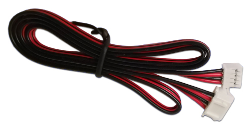
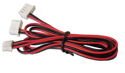
The DCC has 4 Wire Input from the BMS, One comes from the discharge & the other from charge.
In Separate Port, the wire harness is split one plug to BMS, one plug to Discharge side of DCC & one plug to Charge side DCC.

Common Port Wire & Separate Port Wire:
DCC-CableCommon.jpg
DCC-CableSeparate.jpg
Brilliant. Thank you. That answers my question. So you can shut off charging while maintaining discharge. I'll be ordering the 2 x DCC option then.
 
Perhaps a quite ignorant question: can the Chargery BMSs, such as the BMS8T-300, be used without DCCs? I've read through this thread and am not sure that I understand the benefits of using DCC(s).
 
Back
Top