diy solar

diy solar

Lishen 272AH thread?

Last edited:
If I use 1/4" for the shorter inter-connects, should I just to 1/2" or will 3/8" work? Based on what I'm seeing at onlinemetals.coms, my only choice for those thicknesses are pure copper.
Here is a great resource for looking at the capabilities of copper bus-bars
https://diysolarforum.com/resources/busbar-selection-table.104/

Notice that both thickness and width make a difference. I have often wondered if adding thickness or width might be better and keep coming to the conclusion that it only matters in one way: Be sure that the copper is wide enough that the holes don't eat up too much of the cross section of the bar.

> If I use 1/4" for the shorter inter-connects, should I just to 1/2" or will 3/8" work?

What is your expected max sustained current? Judging on the inverter I will assume 140A

On the shorter 'boxed' busbars, there are four separate 'searial' interconnects with a 'voltage balance' parallel interconnect on either end. That is a lot of copper and the arrangement minimizes voltage differences so these can be relatively thin. You would be fine with 1/8" by 3/4". More than that is overkill.... spend the money elsewhere.

The voltage drop problem really only presents itself on the 'End' Busbars and the 8 hole busbars. (With the 8 hole bars being the worst.) If you went 1/4x1 on those you should be fine. 3/8x1 if you want to be sure, (There is no thickness that eliminates the issue, but at some point the voltage drip becomes small enough that it does not matter.


Do you think I could use something to polish the silver to retard tarnishing?
I have no direct experience with silver plate so I am not a good person to ask...... but here are some thoughts.

1) You want clean bare metal against clean bare metal. Anything in between is going to add resistance.
2) A common practice in marine environments (where corrosion is a big issue) is to smear it over with dielectric grease after the busbars are installed and tightened down. This prevents oxygen from getting into the junction. The problem is that dielectric grease is non-conducting so if you ever take it apart, you really must thoroughly clean everything with a solvent before you put it back together. if a little of the grease gets in the junction it could create a bad joint.

Personally I would either stick with copper (Copper oxide is still a reasonable conductor) If I was worried about corrosion I would use tin plated or zinc plated copper.
 
You sound like you may have more experience than I on integrating CAN BUS messages. I do know that Victron has done an integration with an Orion BMS using a display that speaks translates CAN messages to the Victron proprietary protocol. I seem to recall one other with an Orion. I will look through the forum and see if I can find it.
I have an Orion BMS and love it. Orion has a lot of documentation about their CAN messages and you can actually see the CAN messages on the Orion PC interface program. My issue has been that Outback has not been open about that on the inverter side.
Seems like a lot of the bigger Inverter mfgs are tight-lipped with their protocol. I was close to going with Victron for the integration aspects and there's a ton of practical information on the InterWebs.

The convenient aspect of my current setup, I already have the Conext Gateway2. I didn't realize it could integrate the BMS with the inverter using CAN or MOD bus. I think CAN is a bit easier (and probably has more functionality.) I think with the new firmware update, I can also control the MPPT CC's too.

I was leaning towards the Orion, but the price tag was up there compared to some of the others but probably right there with Batrium. I haven't seen much else that can compete with those - maybe REC.
 
Last edited:
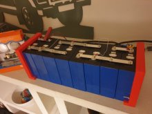
I'm doing another test.. on eight cells 2p4s now..
View attachment 30205
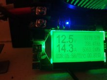
View attachment 30206
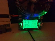
Voltage of the Chinese capacity tester is off a bit..
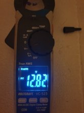
View attachment 30207

I'll let you know the results tomorrow!
Where did you get those orange end brackets? They look like a nice way to clamp the cells together.

Also, could you do me a big favor?
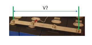
While the system is under full load, use a sensitive volt meter and measure the voltage drop across those long bus bars. (And let me know what the current is when you measure it)

1607897270761.png
I have been contemplating parallel cells lately and I have to wonder how good the long busbars are at keeping the voltage the same across several terminals, particularly when there are 'connections' between the individual small bus bars. With the kind of currents we drive, even a very small resistance can create a noticeable voltage drop.

If the voltage drop is big enough to care about, this layout could significantly reduce the problem:

1607897909184.png
 
I have been contemplating parallel cells lately and I have to wonder how good the long busbars are at keeping the voltage the same across several terminals, particularly when there are 'connections' between the individual small bus bars. With the kind of currents we drive, even a very small resistance can create a noticeable voltage drop.
I am interested also. On the other hand, since these are serial connections what assumption is being made about the voltage that the serial connection is carrying. Is it the voltage of the pack? If it is the pack voltage how significant is the voltage drop? My ability to apply Ohms law is a bit rusty.
I remember your earlier comment that the serial buss bars in your diagram should be place on the terminal post first and I will do that in my next reconfiguration. Since I will be fabricating my own buss bars, another option would be a single plate with four holes. Maybe a fifth hole for the BMS connection.
 
Last edited:
I am interested also. On the other hand, since these are serial connections what assumption is being made about the voltage that the serial connection is carrying. Is it the voltage of the pack? If it is the pack voltage how significant is the voltage drop? My ability to apply Ohms law is a bit rusty.
I remember your earlier comment that the serial buss bars in your diagram should be place on the terminal post first and I will do that in my next reconfiguration. Since I will be fabricating my own buss bars, another option would be a single plate with four holes. Maybe a fifth hole for the BMS connection.
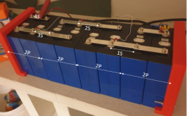
The picture is showing a 2P4S pack.
1607904440835.png

Each of those long busbars are providing a series connection and two parallel cell connections.
1607904975060.png

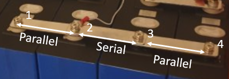
When the battery is under load current will be coming out of terminal one and going toward terminal 2.
Terminal 2 will also be supplying current so between terminal 2 and 3 you will get twice the current.
Terminal 3 is a negative post so half the current will go into terminal 3 and the remainder will go into terminal 4.

Edit: I see I have the neg and positive reversed from what is in the pic, but it does not really change the analysis.
(Why the H*@% do they make the positive post black?.....that just seems soooooo wrong)


There is resistance in the busbars and the connections between the bus bars, so there will be some voltage drop.
We can do a first order approximation model of the circuit like this:
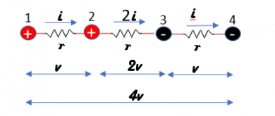
1607905368631.png

Voltage(v) = Current (i) x Resistance r

So the voltage between post one and 2 is v=i x r. Between 2 and 3 the voltage will be 2i x v or 2V. Between 3 and 4 the current is back down so the voltage is back down to i x r = v. Adding them all up, we get v+2v+v or 4V across the whole busbar.

Without going into the mind numbing details, with this model the voltage drop between two parallel cells is 2v (1v on each side).... but we don't know what V is and we don't know what r is so we can not calculate it. We can only make swags like I did in the previous post.

I don't currently have the cells on hand to measure it but since you have the set-up if you could measure it, we could get a feeling for the voltage drop and whether it is significant enough to worry about. It would also let us calculate an approximation of r so we can extend the model to longer busbars.

Once you have your home made bus bars, you can do the same experiment and see how big of a difference it makes to have a single big bar verses 3 smaller stacked bars.

Note: With zero current there will be zero voltage drop. The voltage drop will only show up under load.... for this experiment, the heavier the load the better.

Note: No big deal if you can't do it..... I'll do it with the next batch of cells I buy.
 
Last edited:
Thanks for the illustration. I am a graphical learner and those pictures help my comprehension, I presume my question about the total voltage across the serial interface does not affect the voltage drop calculation? The other question that has been rattling around in my head since your post #52 is the question about voltage drop from one end of the long buss bar to the other end. I am not sure it matters because by the time the voltage gets to the serial connection the voltage drop is only affected by the distance of that connection. Is my thinking correct? In your example I think that the voltage drop would only be one volt not the sum of all the other voltage drops. That is what I am trying to get my head around.
I can see that the cells at the end of the buss bars might have to send more current under load to make up for the resistance from cell 1 to cell 2 and from cell 4 to cell 3. But the voltage drop from cell 2 to cell 3 is only affected by the resistance of that part of the buss bar. In any event as you pointed out earlier in post # 52 it is very small. I am not sure any difference is going to affect my layout.
 
Last edited:
Thanks for the illustration. I am a graphical learner and those pictures help my comprehension, I presume my question about the total voltage across the serial interface does not affect the voltage drop calculation? The other question that has been rattling around in my head since your post #52 is the question about voltage drop from one end of the long buss bar to the other end. I am not sure it matters because by the time the voltage gets to the serial connection the voltage drop is only affected by the distance of that connection. Is my thinking correct?
I can see that the cells at the end of the buss bars might have to send more current under load to make up for the resistance from cell 1 to cell 2 and from cell 4 to cell 3. But the voltage drop from cell 2 to cell 3 is only affected by the resistance of that part of the buss bar. I am not sure any difference is going to affect my layout.
You are correct, the drop from 2 to 3 is not affecting the balance between parallel cells. However the voltage between 1&2 or 3&4 can effect the balance.

The reason measuring the whole length is of interest is that we are dealing with small voltages and the whole busbar gives us a larger voltage to measure. Once we know the voltage of the whole busbar we can divide it by 4 to get the value of v between 1&2 or 3&4. We can also figure out the resistance we are dealing with.

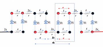
BTW: The model of the whole battery looks like this:

1607911836535.png
Remember: In the model above 'v' is a variable and 4v is 4 times whatever the value of the variable is. (4v is *not* 4 volts)

If you look at the two cells that are outlined, you see that the model predicts a 1v drop between the negative terminals and a 1v drop between the positive terminals (a total of 2v between the cells).

In earlier posts, we were discussing 4 cells in parallel. The problem grows rapidly with each cell in parallel and with 4 cells in parallel the model predicts a 12v difference between the two end cells of the grouping....so you can see why I am interested in getting a handle on this.
 
You are correct, the drop from 2 to 3 is not affecting the balance between parallel cells. However the voltage between 1&2 or 3&4 can effect the balance.
Thanks for clarifying that and the use of the v for variable not volts. I don't think I will ever go above 4 cells in parallel. I do see some of these guys putting together 18650 packs and feeding the common buss bars from both ends to reduce the resistance.
 
Thanks for clarifying that and the use of the v for variable not volts. I don't think I will ever go above 4 cells in parallel.
Sorry.... I sometimes go down these technical rabbit holes and just assume everyone is following.... I need to work on that.
 
Sorry.... I sometimes go down these technical rabbit holes and just assume everyone is following.... .
No worries. My apologies also to the OP but this may help others. The important issue is being mindful of buss bar resistance. This will inform my pack layout during the next configuration.
 
Effectively what's happening is you're increasing the cell resistance the further away from the serial connection you go. It's like having mismatched IR for cells. It becomes more important the more current you draw because the closest cell will take the brunt of discharge/charge. They'll all eventually catch up when idle, but the closest cell takes the most current and the furthest cell takes the least.

I'm soon going to my first parallel cell configuration (just 2p) and I just might use wires between cells (for various reasons, including this one), so I can parallel the cells AND run a wire from each of the first two cells to each of the next two cells. This will give me equal electrical resistance between all cells. Effectively recreating the electrical layout in post 67 without needing to resort to a physically difficult layout (with a 16s system).
 
This was a bit of a dissapointment, test stopped at 501Ah.. My first test with four of these eight cells came out at 282 I believe.. So the problem must lay in the added cells.. This morning there was 15 millivolts difference between the cells, so not very much. Had to go to work so did not have time to investigate further.. I think i will have to redo the test with a computer connected to log the voltages and see when the problem arises.

I have measured the voltage drop across the bushbar at 50A charge rate, and it is 37mv.. Should that improve if I made new solid one piece bushbars from copper?

The end supports are 3d printed, I've made them myself.. 1,5cm thick with holes for threaded rod m6. I can share the files here if anyone is interested.20201214_080152.jpg
 
I have now sanded all bus bars en battery posts, now the biggest voltage drop over the longest bus bar is 7mv at 50A
Do you think that will be low enough?
 
Back
Top